Announcement

Collapse
No announcement yet.

The Red Drift ///Machine - 2026 NASA TT4 adventures

Collapse
X
 
  • Filter
  • Time
  • Show
Clear All
new posts

  • bigjae46
    replied
    EDIT: Added some explanation on how to work with foam in an infusion or wet lay.

    Progress towards NASA Jan 30th...

    Splitter is made and came out great! The spread tow fabric looks outstanding as always!

    Foam core cut and shaped

    Click image for larger version  Name:	IMG_5545.jpg Views:	20 Size:	86.6 KB ID:	340672

    This was a wet layup and the vacuum bag. Not 100% optimal but the foam core presents some infusion challenges without infusion channels. The foam core is impermeable so the large flat surface will not enhance resin flow in an infusion. Some resin with flow through the carbon except for any spot where layers of carbon tows line up. And then any air will have an extremely hard time to flow towards the vacuum side.

    I drilled over a hundred holes in the foam to allow air to flow from the mold surface. Even then, I didn't want to risk large epoxy voids in an infusion. The holes in a wet layup will allow for excess resin and air to be pulled through the holes and towards the vacuum. But damn...a wet lay is a LOT more work! Critical to use a very slow hardener and mix in smaller batches to prevent exotherm. I used Pro-Set extra slow so I had 3 hours.

    If you do a wet layup, it is important to thoroughly roll the layers under the foam to remove as much air as possible to minimize the risk of air being trapped under the foam. Air creates resin voids which results in a weaker part.

    Click image for larger version  Name:	IMG_5588.jpg Views:	21 Size:	93.2 KB ID:	340668

    i am installing tunnels but the challenge with the E46 is the short overhang. The tunnels sit right where everyone places the splitter mounts. So I'm using a bridge which I will bond and bolt to allow for an optimal mounting location.

    Click image for larger version  Name:	IMG_5589.jpg Views:	20 Size:	82.7 KB ID:	340674

    Click image for larger version  Name:	IMG_5590.jpg Views:	21 Size:	100.0 KB ID:	340670

    Less than 9lbs!!!

    Click image for larger version  Name:	IMG_5591.jpg Views:	22 Size:	55.5 KB ID:	340669

    AND...AJ Hartman rear wing. Somethings are better left to the professionals. A rear wing is one if those things. Expensive but the E46 kit is comprehensive. Took an hour to mount. Easy peasy!
    Click image for larger version  Name:	IMG_5561.jpg Views:	21 Size:	116.8 KB ID:	340671

    Click image for larger version  Name:	IMG_5560.jpg Views:	22 Size:	114.9 KB ID:	340673
    Last edited by bigjae46; 01-22-2026, 06:02 AM.

    Leave a comment:


  • bigjae46
    replied
    Making a CF version of Bry5on's wheel well plates. It came out ok, needs to be a little thicker and needs a quasi isotropic layup.

    Click image for larger version

Name:	IMG_5540.jpg
Views:	231
Size:	139.8 KB
ID:	340661
    Click image for larger version

Name:	IMG_5546.jpg
Views:	204
Size:	129.8 KB
ID:	340663

    Click image for larger version

Name:	IMG_5571.jpg
Views:	230
Size:	125.1 KB
ID:	340662

    Click image for larger version

Name:	IMG_5570.jpg
Views:	229
Size:	119.7 KB
ID:	340664

    Leave a comment:


  • bigjae46
    replied
    2nd half of the mold is done. Once again, I forgot to install drive pins in the negative side to get the part out. So I had to drive the part out by threading a bolt in. I chipped the mold around the bolt hole which will require a repair. It will be a pain but maybe I'll learn my lesson this time.

    Also didn't catch a negative draft around the inner opening. So I need to make 2 small repairs on each side.

    Overall they came out really good!

    Onto making the repairs, calculating the volume, and then making a part sometime in the future. Just not sure when, gotta get ready for NASA in 3 weeks among other things.

    Click image for larger version

Name:	IMG_5511.jpg
Views:	297
Size:	108.8 KB
ID:	332857

    Leave a comment:


  • bigjae46
    replied
    Originally posted by Bry5on View Post

    You could also do a hybrid. Fill the tight corners with putty to open up the radii and make release easier with little weight penalty.
    I would more likely do that for the first half but I'm willing to risk it for the 2nd half. The 2nd half uses about 1/3 the casting resin and is relatively quick to setup. Most of the work is in the first half of a compression mold.

    Leave a comment:


  • Bry5on
    replied
    Originally posted by bigjae46 View Post

    I did but I don't think it will be a huge issue. I use release wax and then a chemical release. So I just need to spend more time getting the wax into the corners. Then the chem release is a solvent so it should provide a good backup to the corners and edges.
    You could also do a hybrid. Fill the tight corners with putty to open up the radii and make release easier with little weight penalty.

    Leave a comment:


  • bigjae46
    replied
    Originally posted by heinzboehmer View Post

    Maybe consider making the underside flat? The details are just there to save weight for the cast part.

    (which means you'll end up with a heavier carbon part if you fill that in, of course)
    I did but I don't think it will be a huge issue. I use release wax and then a chemical release. So I just need to spend more time getting the wax into the corners. Then the chem release is a solvent so it should provide a good backup to the corners and edges.

    Leave a comment:


  • heinzboehmer
    replied
    Originally posted by bigjae46 View Post
    Half way done! The 2nd half of the mold will be a PIA. All of the little details will provide opportunities for a bad release.
    Maybe consider making the underside flat? The details are just there to save weight for the cast part.

    (which means you'll end up with a heavier carbon part if you fill that in, of course)

    Leave a comment:


  • bigjae46
    replied
    Working on CF strut tower plates. Making a compression Adding a tab to make a triangular brace. The layup will be long strand forged carbon with nut inserts molded in. I have no idea if the insert will hold up. Worst case, I drill them out and bond a stud plate underneath.

    Half way done! The 2nd half of the mold will be a PIA. All of the little details will provide opportunities for a bad release.

    Click image for larger version

Name:	IMG_5503.jpg
Views:	261
Size:	68.7 KB
ID:	332746

    Click image for larger version

Name:	IMG_5506.jpg
Views:	289
Size:	95.4 KB
ID:	332747

    Leave a comment:


  • bigjae46
    replied
    The car 100% needs a suspension refresh. The car is no longer comfortable to drive and there is a noticeable difference between front and rear tire wear. You can feel the suspension bottom out over curbs and bumps. It now hurts my back, the ride used to be more comfortable than my Dinan stage 2 E90 M3. Now just waiting on Jalal (aka Shaikh) to do his FCM stage 3 magic.

    AJ Hartman rear wing is on order, might be here in 2 weeks. Also time for a front splitter upgrade. I have to get into compliance with the 6" limit for NASA TT4 and will also add some tunnels. My splitter is 6.25" along 14" on the edge of the splitter...a 1/4"!!! But I don't want to hear any shit so better to be safe than sorry.

    FYI...A 6" splitter is a bad in-between for NASA. Needs to be a little less than 6" for TT4 or 10"-11" for TT3.

    And finally, I will implement the cheat code - Hoosiers!

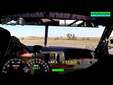
    And It's been a little bit since the last driving video. So if you can't sleep just watch this for a minute.


    Leave a comment:


  • bigjae46
    replied
    It is a mad dash to NASA on Jan 30th and to finish a bunch of molds before Apr 30th when it starts to get hot in TX. Working with polyester resin in the heat sucks. Make molds Jan to Apr, Carbon parts May to Oct, more molds Nov to Dec.


    Air dam is trimmed and finished.

    Click image for larger version  Name:	IMG_5484.jpg Views:	0 Size:	31.2 KB ID:	332317
    Click image for larger version  Name:	IMG_5485.jpg Views:	0 Size:	32.8 KB ID:	332320

    1.2 lbs...should save me 1-2lbs over my cheap amazon.com aero version.

    Click image for larger version  Name:	IMG_5486.jpg Views:	0 Size:	59.5 KB ID:	332322

    Separate foglight block offs.

    Click image for larger version  Name:	IMG_5487.jpg Views:	0 Size:	84.3 KB ID:	332319

    Front bumper molds...3rd try...done. 1st attempt - the flanges need more support so they sagged when I was laminated the FG. 2nd attempt - I used some borderline release agent. Apparently, it was on the wrong side of the borderline so the part stuck to the mold and destroyed it.

    The plan is to pull a part and mold the air dam and some tire spats into one piece. Finally, make a mold of the entire assembly.

    Click image for larger versionName:	IMG_5492.jpgViews:	0Size:	114.7 KBID:	332316

    Single air duct and brake deflector molds done. Still working on the wheel well plates. Had a gel coat issue so I'm starting over.

    Click image for larger version  Name:	IMG_5489.jpg Views:	0 Size:	91.2 KB ID:	332321
    Attached Files
    Last edited by bigjae46; 01-05-2026, 11:05 AM.

    Leave a comment:


  • bigjae46
    replied
    Air dam is almost done. Needs a little more trimming.

    Click image for larger version

Name:	IMG_5442.jpg
Views:	367
Size:	122.6 KB
ID:	329443

    Click image for larger version

Name:	IMG_5443.jpg
Views:	347
Size:	80.4 KB
ID:	329441

    I'm happy with the brake deflectors. So mold making has started! I think I have an idea for mounting. More to follow!

    Click image for larger version

Name:	IMG_5445.jpg
Views:	365
Size:	91.3 KB
ID:	329440

    Taking Bryson's reinforcement plate and making a CF part!

    Click image for larger version

Name:	IMG_5444.jpg
Views:	333
Size:	80.2 KB
ID:	329444
    Attached Files

    Leave a comment:


  • bigjae46
    replied
    I deleted the hood shocks and always had issues with opening the hood after a track session to let it cool off.

    well...no more! Cost about $30. It locks into the aerocatch latch and the pin. Wind proof!

    Click image for larger version

Name:	IMG_5439.jpg
Views:	340
Size:	97.4 KB
ID:	329434
    Click image for larger version

Name:	IMG_5441.jpg
Views:	347
Size:	138.9 KB
ID:	329432
    Click image for larger version

Name:	IMG_5440.jpg
Views:	360
Size:	165.8 KB
ID:	329433

    Leave a comment:


  • bigjae46
    replied
    Originally posted by heinzboehmer View Post
    Hell yeah! Awesome to see the design being put to use.
    Your design is extremely well thought out...it definitely deserves to be used...A LOT!

    I'm thinking that making the stud plate from aluminum and the base plate from carbon would be an excellent balance especially considering the cost of machining the base plate from aluminum.

    Leave a comment:


  • heinzboehmer
    replied
    Hell yeah! Awesome to see the design being put to use.

    Leave a comment:


  • bigjae46
    replied
    I molded in threaded inserts instead of studs - studs were $21 a piece! Then I’m going to bond the 2 parts together since I don’t have to worry about servicing my wipers are blower motor.

    I’m going a different route for the strut bar plates. I am planning to bolt the extra bars onto the existing studs. I will need longer studs and I think I may need to make the strut bar end plates from something stronger - carbon fiber!

    For the bars, I might use some tubes and rod ends from here: DragonPlate | Engineered Carbon Fiber Composite Sheets, Tubes and Structural Components | Made in USA​. Then modify the rod ends to be a negative of the OE strut bar so it fits on top.

    Here is the wild part. I've been trying to figure out a good way to vent the radiator out of the hood while keeping the M3 hood bulge. The leading edge of the bulge is right where I'd duct the radiator out. Maybe I can make the strut bars into an H and then use the strut bars to mount the radiator duct and vent the radiator out of the bulge. What I don't know is how much it would screw up the aero going up over the windshield to the rear wing. Not a big concern but something to consider.

    I might be able to solve two issues at once, minimize added weight, improve front end aero, cooling, and chassis stiffness and maintain serviceability and a key M3 cosmetic feature.

    Last edited by bigjae46; 09-23-2025, 05:44 PM.

    Leave a comment:

Working...
X