Announcement

Collapse
No announcement yet.

Need help doing vanos test with INPA

Collapse
X
 
  • Filter
  • Time
  • Show
Clear All
new posts

  • MParallel
    replied
    Originally posted by heinzboehmer View Post

    I'm pretty sure JOB_STATUS is referring to the routine having been completed successfully (i.e. the program on your computer ran through all the tests it had to perform) and not to the test having passed....
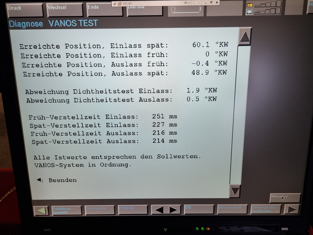
    Correct. This is where DIS shines. It's doesn't only tell you what is wrong, but also explains how to solve with all its Test Schedules. And regarding the DIS Vanos test, does tell if values are within what is OK or not.

    For example, here in German it says at the end that all Should-be and Actual values correspond.
    Leave a comment:


  • Tomba
    replied
    Originally posted by MParallel View Post

    Wow that was quick. Thanks a ton.
    Your welcome

    Just so I understand correctly, I can execute this in INPA, or do I need to run this in Tool32?
    Tool32 by opening test.

    From BMW info, the vanos spread is (a little) different S50B32 vs S54. Since I see these target values being mentioned for the S54, does this goes correctly?
    See values above.
    Intake spread is 70-130 = 60° degrees. Exhaust spread is -114 - -76 = 38°
    Typical OK values intake would be advanced -1 to +1, retarded 59 to 61
    Exhaust i would expect advanced -1 to 1, retarded 38 to 41. Like the MSS54 I suspect the retarded value higher.
    Response times would be ok below <250-300ms.
    The leak check I am not really sure. I don't know how DIS calculates this yet.

    Although these aren't 'hardcoded' numbers mentioned in the testfile, so I guess this is just what is inside the MSS50 (grp/ecu) files?
    The evaluation is more done inside DIS eventually when running these. I suspect there would be error code in the ECU if the desired position is not reached but most of the times these are quite long compared to the desired response time we want.

    EDIT: my bad, I now see on page one the instructions to run the .tst file. It's in Tools32. Well that's still easier then firing up DIS.
    Please upload the results here so we can check them.

    Leave a comment:


  • MParallel
    replied
    Originally posted by Tomba View Post

    Sure, in attachment.
    includes ECU version check, coolant & oil temperature measurement before starting the test.
    First E (einlass) intake is checked, than A (auslass) exhaust
    Target values (E=60-0) (A=40-0), response times <250-300ms
    ******* Note this test procedure is for MSS50 ********
    Wow that was quick. Thanks a ton.
    Just so I understand correctly, I can execute this in INPA, or do I need to run this in Tool32?
    From BMW info, the vanos spread is (a little) different S50B32 vs S54. Since I see these target values being mentioned for the S54, does this goes correctly?
    Although these aren't 'hardcoded' numbers mentioned in the testfile, so I guess this is just what is inside the MSS50 (grp/ecu) files?

    EDIT: my bad, I now see on page one the instructions to run the .tst file. It's in Tools32. Well that's still easier then firing up DIS.
    Last edited by MParallel; 12-01-2022, 05:44 AM.

    Leave a comment:


  • Tomba
    replied
    Originally posted by MParallel View Post

    Tomba, would you be able to make a custom Vanos test file like you did for the S54. but for the EU S50B32?
    Sure, in attachment.
    includes ECU version check, coolant & oil temperature measurement before starting the test.
    First E (einlass) intake is checked, than A (auslass) exhaust
    Target values (E=60-0) (A=40-0), response times <250-300ms
    ******* Note this test procedure is for MSS50 ********
    Attached Files
    Last edited by Tomba; 12-01-2022, 05:23 AM.

    Leave a comment:


  • MParallel
    replied
    Just a tiny sidenote: *.ipo files are generated from *.ips files. If you can get your hands on these...impossible. I haven't seen these being leaked.

    Tomba, would you be able to make a custom Vanos test file like you did for the S54. but for the EU S50B32?

    I always need to fire up DIS to perform the Vanos test, but if this could be done in INPA, that would just be great. I've done tons of work with INPA/DIS/NCS Expert, but never with Tools32.

    I was already delighted I found a .ipo file for the EU SMG (my E36 M3 is SMG) that is not referenced in the INPA menu. So I changed the .txt file so this file can be executed and to my surprise it has many SMG test functions, but for each part individually, instead of having to run the complete calibration in DIS for the whole system. Only the bleed functions stop, so I guess this was a file that was worked on, but never got finished.
    I mainly use it to do a quick relearning of the clutch bitepoint, which alone, can not be done in DIS. And I don't need to recalibrate things like throttle pedal, shifter, etc each time.
    Last edited by MParallel; 12-01-2022, 04:29 AM.

    Leave a comment:


  • JBAshland
    replied
    So when the splined shaft touched on the pump disk, the piston doesn't protrude out of the vanos? It must, although less than 2mm, as I don't think the designer wanted to use the pump disk instead of the cap to set the max retarded for the EX cam.
    It does protrude very slightly - maybe .5mm whereas the Intake is @ 2mm. There are also small cylindrical nubs in the center of the cap that protrude outwards that must provide the 'stop'. You can see witness marks on the pistons if you look closely.

    Leave a comment:


  • sapote
    replied
    Originally posted by JBAshland View Post

    FYI - In my case, even after removing the Vanos and checking it out on the bench, I could see that the splined shaft along with the connection to the piston could not physically move forward 2mm out. It stops at flush as the front/flat side of the helical gear stops at the oil pump disc whereas the intake piston will protrude 2mm. I searched around a little bit and from various videos and pictures I saw, this was consistent. Sounds like you have seen otherwise?
    So when the splined shaft touched on the pump disk, the piston doesn't protrude out of the vanos? It must, although less than 2mm, as I don't think the designer wanted to use the pump disk instead of the cap to set the max retarded for the EX cam.
    Last edited by sapote; 10-17-2022, 12:16 AM.

    Leave a comment:


  • JBAshland
    replied
    I don't see why the splined shaft cannot move forward and push the EX piston 2mm out
    FYI - In my case, even after removing the Vanos and checking it out on the bench, I could see that the splined shaft along with the connection to the piston could not physically move forward 2mm out. It stops at flush as the front/flat side of the helical gear stops at the oil pump disc whereas the intake piston will protrude 2mm. I searched around a little bit and from various videos and pictures I saw, this was consistent. Sounds like you have seen otherwise?

    Leave a comment:


  • sapote
    replied
    Originally posted by JBAshland View Post
    1. I was not able to push the EX piston 2mm forward of the vanos module - it was basically flush and after taking off the Vanos, I could see that the EX piston would only travel flush (maybe slightly extruded) until it was impeded on the other/engine side.
    2. It did show that it was advanced - it was pretty far off...so I have likely been chasing issues, throwing parts at it as opposed to checking what was really going on.
    1. I don't see why the splined shaft cannot move forward and push the EX piston 2mm out. I guess turning the EX cam CCW to move the splined shaft forward may not be a good idea in all cases, because the splines helical cut is not a steep angle, and so it is hard to translate rotation to linear motion in this case, especially if the piston has new seals and little tight. In this case, I should have asked you to remove the vanos module off the head, then manually pull the splined shaft out (but not completely out of the hub) while rotate the EX cam CCW, then install the vanos and the EX piston should be protruding out.

    2. This case shows that it is not a reliable way to check vanos timing by just rotate the crank to TDC compression then check the cams with the bridge tool pin. As in this case, the OP could not push the piston pass the vanos with the removed cover. So it is better to remove the piston covers then push the pistons out by 1 or 2mm, then install the covers back and this gaurantee the cams are at their max retarded position before checking with the bridge pin.


    Leave a comment:


  • JBAshland
    replied
    Originally posted by sapote View Post

    So what was the timing check result? Did it show that the EX cam was too advanced after bolting down the vanos piston caps? Were you able to push the EX piston 2mm forward of the vanos module?
    It did show that it was advanced - it was pretty far off...so I have likely been chasing issues, throwing parts at it as opposed to checking what was really going on. I was not able to push the EX piston 2mm forward of the vanos module - it was basically flush and after taking off the Vanos, I could see that the EX piston would only travel flush (maybe slightly extruded) until it was impeded on the other/engine side. The Intake piston, 2mm no problem. At one point I was doubting whether I had the correct splined gears on the intake vs exhaust side, but they were in the right place. Either way, thanks for all your help.

    Leave a comment:


  • sapote
    replied
    Originally posted by JBAshland View Post
    I retimed it last night and got the following results
    The new result looks good:
    IN [-1 to 58]
    EX [-1 to 47]

    So what was the timing check result? Did it show that the EX cam was too advanced after bolting down the vanos piston caps? Were you able to push the EX piston 2mm forward of the vanos module?

    Leave a comment:


  • JBAshland
    replied
    I retimed it last night and got the following results (after clearing adaptations) whereas results prior to clearing adaptations were pretty off as I would think would be expected. No error codes as yet, so keeping my fingers crossed there. Results not perfect, but better? Thanks to you both for all of your help.

    Test file : C:\EDIABAS\ECU\MSS54_VANOS_TESTS.TST
    Start : 14.10.2022 11:47:38.8
    Nr 1( 1) : 14.10.2022 11:47:38.9
    apiJob("mss54ds0","STEUERN_EVANOS1_FRUEHANSCHLAG", "","")
    JOB_STATUS = OKAY
    EVAN_ISTWERT = -1 FF FF FF FF ÿÿÿÿ
    EVAN_SOLLWERT = -10 FF FF FF F6 ÿÿÿö
    EVAN_ISTWERT_EINH = Grad KW
    EVAN_SOLLWERT_EINH = Grad KW
    Nr 2( 1) : 14.10.2022 11:47:44.2
    apiJob("mss54ds0","STEUERN_EVANOS1_SPAETANSCHLAG", "","")
    JOB_STATUS = OKAY
    EVAN_ISTWERT = 58 00 3A .:
    EVAN_SOLLWERT = 75 00 4B .K
    EVAN_ISTWERT_EINH = Grad KW
    EVAN_SOLLWERT_EINH = Grad KW
    Nr 3( 1) : 14.10.2022 11:47:49.5
    apiJob("mss54ds0","STEUERN_EVANOS1_VERSTELLZEIT"," ","")
    JOB_STATUS = OKAY
    EVAN_VERSTELLZEIT_FRUEH = 250 00 FA .ú
    EVAN_VERSTELLZEIT_SPAET = 234 00 EA .ê
    EVAN_VERSTELLZEIT_FRUEH_EINH = ms
    EVAN_VERSTELLZEIT_SPAET_EINH = ms
    Nr 4( 1) : 14.10.2022 11:47:55.7
    apiJob("mss54ds0","STEUERN_EVANOS1_DICHTHEIT",""," ")
    JOB_STATUS = OKAY
    EVAN_STATUS = EVANOS-1-Einheit vorzeitig weggedriftet
    Nr 5( 1) : 14.10.2022 11:48:10.1
    apiJob("mss54ds0","STEUERN_AVANOS1_FRUEHANSCHLAG", "","")
    JOB_STATUS = OKAY
    AVAN_ISTWERT = -1 FF FF FF FF ÿÿÿÿ
    AVAN_SOLLWERT = -10 FF FF FF F6 ÿÿÿö
    AVAN_ISTWERT_EINH = Grad KW
    AVAN_SOLLWERT_EINH = Grad KW
    Nr 6( 1) : 14.10.2022 11:48:15.4
    apiJob("mss54ds0","STEUERN_AVANOS1_SPAETANSCHLAG", "","")
    JOB_STATUS = OKAY
    AVAN_ISTWERT = 47 00 2F ./
    AVAN_SOLLWERT = 55 00 37 .7
    AVAN_ISTWERT_EINH = Grad KW
    AVAN_SOLLWERT_EINH = Grad KW
    Nr 7( 1) : 14.10.2022 11:48:20.6
    apiJob("mss54ds0","STEUERN_AVANOS1_VERSTELLZEIT"," ","")

    Leave a comment:


  • sapote
    replied
    Originally posted by JBAshland View Post
    The intake side is protruded about 2 mm, but the exhaust will go no further. This leads me to believe that the timing is set too advanced
    Look at the EX splined shaft and see if it had protruded far enough. If you turn the EX cam far enough it should push the splined shaft off the hub which you don't want to push this far. The spines can jam tight so you need rock the cam to push it out.

    Yeah, 13v at the cam sensor is a healthy supply.

    Leave a comment:


  • JBAshland
    replied
    Originally posted by sapote View Post

    Low voltage supply to the cam sensors might cause the sensor output signal out of spec, and this can cause the DME to read the cam timing incorrectly. so with the engine idling, measure the voltage at the fender jump post, then compare to the voltage at one of the cam sensor pin (3 pins with 12v, GND, and signal output and so the 12v should be a DC signal, either 5v or 12v I don't remember).
    Remember to provide the year/month build, SMG or manual so I and others can look up the correct wiring diagram for the cam sensors.
    Thanks Sapote. I think that may have been a red herring as I was able to reproduce the errors (after clearing) past idle and with checking the voltage (I could see reported voltage at the sensor was above 13 volts. I checked the timing per your procedure (at least started to) and I can't even get the exhaust piston to protrude past the cylinder. The intake side is protruded about 2 mm, but the exhaust will go no further. This leads me to believe that the timing is set too Click image for larger version

Name:	vanos1.jpg
Views:	1142
Size:	76.7 KB
ID:	188398 advanced on the exhaust as we have surmised?

    Leave a comment:


  • sapote
    replied
    Originally posted by JBAshland View Post
    Surprisingly, no adjustment was done. It is almost as if the cam timing slipped?

    What I also seem to have found is that the Cam sensor codes 10 and 15 will consistently appear (after clearing) on startup after letting the car sit. If I clear the codes and then allow it to run and then check again, the codes will not come back - in the garage idling at least. INPA reports voltage to the sensor and RPM at the time of the error, and the voltage is less than 12 volts (usually around 11.4).
    Low voltage supply to the cam sensors might cause the sensor output signal out of spec, and this can cause the DME to read the cam timing incorrectly. so with the engine idling, measure the voltage at the fender jump post, then compare to the voltage at one of the cam sensor pin (3 pins with 12v, GND, and signal output and so the 12v should be a DC signal, either 5v or 12v I don't remember).
    Remember to provide the year/month build, SMG or manual so I and others can look up the correct wiring diagram for the cam sensors.

    Leave a comment:

Working...
X