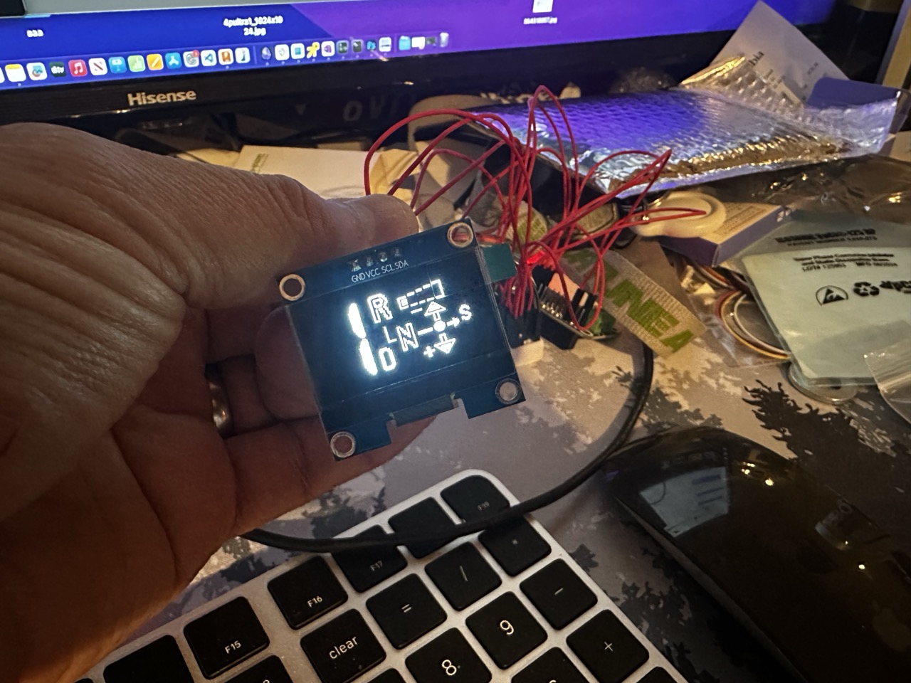
I'm designing a small embedded ESP32 that displays DCT gear, DriveLogic speed/mode, and looks factory in the e46 M3 gauge cluster (replaces the SMG display). Can anybody verify these are correct? (This is a copy of my notes.)
E9x M3 DCT CAN IDs — Gear, DriveLogic Mode & Setting
Primary Message: 0x1D2 (decimal 466) — GEAR_1D2 from KOMBI/cluster
This is the main TCU status message broadcast on the PT-CAN (powertrain CAN). It contains the current gear, shift lever mode, and sport button state.
ShiftLeverPosition values:
ShiftLeverMode (DriveLogic mode) values:
DriveLogic Setting/Level: 0x43F (decimal 1087)
Community sniffing confirms that 0x43F carries the DCT gear and DriveLogic data. Byte 0 (B0) contains the current gear — 0x40 or 64 in decimal means Neutral, with the upper nibble indicating engagement status and the lower nibble the actual gear. Byte 2 (B2) carries the DriveLogic setting/level.
Observed raw data pattern from the forum:
So for 0x43F:
Drivelogic Button Input: 0x198
The Drivelogic rocker switch is wired directly to the GWS (gear selector module), and its presses are transmitted on 0x198 on the PT-CAN. This is an input to the TCU — button press events rather than a status broadcast.
Supporting Gear Messages
Once I get everything working how I'd like, I'll share everything on github.
E9x M3 DCT CAN IDs — Gear, DriveLogic Mode & Setting
Primary Message: 0x1D2 (decimal 466) — GEAR_1D2 from KOMBI/cluster
This is the main TCU status message broadcast on the PT-CAN (powertrain CAN). It contains the current gear, shift lever mode, and sport button state.
| ShiftLeverPosition | bits 0–3 (B0 lower nibble) | See values below |
| ShiftLeverPositionXOR | bits 4–7 (B0 upper nibble) | XOR/checksum of position |
| GearRelated_TBD | bits 12–15 | Partially decoded |
| Counter | bits 28–31 | Rolling counter (0–14) |
| ShiftLeverMode | bits 32–33 | DriveLogic mode — see values below |
| SportButtonState | bit 26 | 1 = active, 0 = inactive |
- 0 = Off
- 1 = P (Park)
- 2 = R (Reverse)
- 4 = N (Neutral)
- 8 = D (Drive)
ShiftLeverMode (DriveLogic mode) values:
- 0 = Normal (D)
- 1 = Sport (S)
- 2 = Manual (M)
DriveLogic Setting/Level: 0x43F (decimal 1087)
Community sniffing confirms that 0x43F carries the DCT gear and DriveLogic data. Byte 0 (B0) contains the current gear — 0x40 or 64 in decimal means Neutral, with the upper nibble indicating engagement status and the lower nibble the actual gear. Byte 2 (B2) carries the DriveLogic setting/level.
Observed raw data pattern from the forum:
- Neutral: 64, 6, 1, ... → B0 = 0x40 (in-gear flag set, gear = 0/neutral)
- 1st gear: 65, 1, ... → B0 = 0x41
- 2nd gear: 66, 2, ... → B0 = 0x42
So for 0x43F:
- B0 (Byte 0): Current engaged gear. Upper nibble = state (0x4x = settled/engaged), lower nibble = gear number (0=N, 1=1st, 2=2nd, etc.)
- B2 (Byte 2): DriveLogic setting/level (1–6 in Manual mode, or the program level in D/S)
Drivelogic Button Input: 0x198
The Drivelogic rocker switch is wired directly to the GWS (gear selector module), and its presses are transmitted on 0x198 on the PT-CAN. This is an input to the TCU — button press events rather than a status broadcast.
Supporting Gear Messages
| 0x1A2 | Gearbox data from DME (includes ManualMode flag, bit 50) |
| 0x3B1 | Gearbox data 2 from DME |
| 0x3B0 | Reverse gear status (bit 6 = 1 when in reverse) |
Comment