Announcement

Collapse
No announcement yet.

Benefits of running THE flap?

Collapse
X
 
  • Filter
  • Time
  • Show
Clear All
new posts

  • 0-60motorsports
    replied
    Originally posted by duracellttu View Post

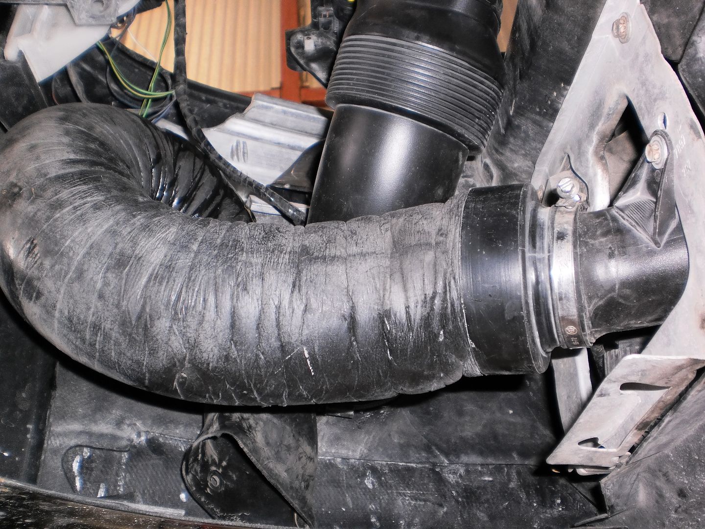
    Any other pictures or details around this mounting bracket? I couldn't find anything on realoem.

    Click image for larger version

Name:	InkedP5080011_LI.jpg
Views:	674
Size:	143.7 KB
ID:	15660
    So there is nothing there on a normal
    m3. You’ll have to either drill it and install it with a nut and bolt or put a stud there and use a nut to secure the hose or it’ll touch the belts. Don’t ask me how I know lol

    Leave a comment:


  • duracellttu
    replied
    Originally posted by 0-60motorsports View Post

    Here you go:
    Any other pictures or details around this mounting bracket? I couldn't find anything on realoem.

    Click image for larger version

Name:	InkedP5080011_LI.jpg
Views:	674
Size:	143.7 KB
ID:	15660

    Leave a comment:


  • duracellttu
    replied
    Originally posted by 0-60motorsports View Post

    Here you go:
    Thanks! Those are really helpful. Is that from a genuine CSL? Just curious.

    Any pics on the #3 top pipe mount in the pic below?

    Click image for larger version

Name:	IMG_2549.JPG
Views:	706
Size:	27.7 KB
ID:	15643

    Leave a comment:


  • 0-60motorsports
    replied
    Originally posted by duracellttu View Post

    I'm currently in discussions with a CSL owner in the UK to get pictures and an understanding on exactly how pipes 9, 10, and 15 are mounted from the factory. I'll be sure to share when I find out. It's been something I've been trying to find out for quite a while.
    Here you go:


    Leave a comment:


  • duracellttu
    replied
    Originally posted by mainstreamer00 View Post

    You could run "9,10,15" in this scenario, which I believe is meant to draw air from below the car/outside engine bay when the flap is closed.
    As said above - for main snorkel intake, could run an Eventuri scoop or piece of ducting to connect with the hole in the top of the brake duct.

    Click image for larger version

Name:	Screen Shot 2020-04-16 at 7.47.30 AM.png
Views:	2829
Size:	354.4 KB
ID:	12565
    I'm currently in discussions with a CSL owner in the UK to get pictures and an understanding on exactly how pipes 9, 10, and 15 are mounted from the factory. I'll be sure to share when I find out. It's been something I've been trying to find out for quite a while.

    Leave a comment:


  • heinzboehmer
    replied
    Originally posted by Cubieman View Post
    Anyone else running the Turner IAT relocation harness along with the Kassel MAP sensor setup?
    I sure wish Kassel would have given some basic instructions, there are 2 wires with little metal "tabbed" ends that terminate in the DME harness, somewhere. Than the third wire on the Kassel MAP setup is simply a T-tap.
    Can anyone tell me if there are any issues using these 2 products together?
    I obviously don't have a complete understanding of the wiring for a CSL box yet. I'd sure like to better understand before I get in there.
    I have read through the posted DIYs and I very much appreciate the info. I am probably making all of this much more complex than need be.
    Heres a picture of the Kassel wiring...
    Click image for larger version Name:	20200421_214845.jpg Views:	0 Size:	134.8 KB ID:	15324
    Click image for larger version Name:	image_5695.jpg Views:	3 Size:	40.1 KB ID:	15328

    This is my current plan:
    - IAT: plug in Turner Harness, done.
    - MAP: (Kassel) wiring as follows

    The MAP sensor is wired to the DME via 3 wires.

    The wires are connected in the following manor:

    MAP Sensor – Pin A to DME – Splice to X60003 Pin 17 (Brown/Orange) or insert a new pin into X60003 Pin 16 – Ground
    MAP Sensor – Pin B to DME – Insert a new pin into X60003 Pin 18 (Yellow) – Signal
    MAP Sensor – Pin C to DME – Splice to X60003 Pin 7 (Red/Green) – Shared Power (5V)
    Wiring the MAP sensor that way should work just fine.

    ​​​Not really familiar with the Turner harness, but I'm assuming it just splits off the wires for the IAT sensor (can't think of what else it would be doing). I would be surprised if combining these two products didn't work.

    Leave a comment:


  • Cubieman
    replied
    Anyone else running the Turner IAT relocation harness along with the Kassel MAP sensor setup?
    I sure wish Kassel would have given some basic instructions, there are 2 wires with little metal "tabbed" ends that terminate in the DME harness, somewhere. Than the third wire on the Kassel MAP setup is simply a T-tap.
    Can anyone tell me if there are any issues using these 2 products together?
    I obviously don't have a complete understanding of the wiring for a CSL box yet. I'd sure like to better understand before I get in there.
    I have read through the posted DIYs and I very much appreciate the info. I am probably making all of this much more complex than need be.
    Heres a picture of the Kassel wiring...
    Click image for larger version  Name:	20200421_214845.jpg Views:	0 Size:	134.8 KB ID:	15324
    Click image for larger version  Name:	image_5695.jpg Views:	3 Size:	40.1 KB ID:	15328

    This is my current plan:
    - IAT: plug in Turner Harness, done.
    - MAP: (Kassel) wiring as follows

    The MAP sensor is wired to the DME via 3 wires.

    The wires are connected in the following manor:

    MAP Sensor – Pin A to DME – Splice to X60003 Pin 17 (Brown/Orange) or insert a new pin into X60003 Pin 16 – Ground
    MAP Sensor – Pin B to DME – Insert a new pin into X60003 Pin 18 (Yellow) – Signal
    MAP Sensor – Pin C to DME – Splice to X60003 Pin 7 (Red/Green) – Shared Power (5V)
    Attached Files
    Last edited by Cubieman; 04-21-2020, 09:22 PM.

    Leave a comment:


  • Bigfoot
    replied
    If you are concerned about make non reversible modifications to your factory MAF loom, it can easily be disconnected from the DME.

    Just label up the DME pin numbers on the loom and keep it with your old air-box.

    Last edited by Bigfoot; 04-21-2020, 09:39 AM.

    Leave a comment:


  • repoman89
    replied
    terra had posted a tip at one point that there’s a rubber grommet going to the DME box on the driver side right next to the fender with an extra little capped off rubber tube. I used that for the flap actuator (or position sensor? Whichever is on the passenger side of the flap). The plastic tubing fits in it perfectly. I also used his tip to create an extra connector in there that can be unplugged to make DME and wiring removal easier, it’s come in handy more than once.

    I snipped the MAF connector off, pulled the extra wires, and reused some for the other flap connector (driver side one). For the IAT I drilled a third hole in that little box on the strut tower and sealed it up with some gasket maker, running the plastic tubing under the airbox to the stock CSL location. My MAP wiring goes through that little box too. Ideally you’d pull it through the grommet on the wiring harness at the back of the engine that 04+ cars used for that crankcase breather valve but you’d definitely have to remove the whole harness for that. Not that it would be that hard to remove.

    My way was clean and stock looking but non reversible. Doesn’t bother me, the intake is on there to stay.
    Last edited by repoman89; 04-21-2020, 07:18 AM.

    Leave a comment:


  • jbfrancis3
    replied
    Originally posted by 0-60motorsports View Post
    Its a great one. I used the embedded image with credit to given to mwstewart.

    Leave a comment:


  • 0-60motorsports
    replied
    Originally posted by Cubieman View Post
    Could anyone happen to point me to the best current DIY for the wiring for the MAP/IAT/FLAP. And actually just the box installation in general as well.

    Mainly just looking for Flap wiring info. I have the turner IAT relocation so that done, have the Kassel MAP sensor, so good there.
    I have been looking at some good posts here:

    Just wondered if anyone saved any CSL box DIYs from the old forums.
    This is mine

    Well here is my DIY attempt at converting my wiring to OEM CSL after replacing my MSS54 with a Terra Modified MSS54HP. I have an OEM CSL Airbox with Flap and all OEM ducting etc.. Starting to untangle the mess LOL..... http://i17.photobucket.com/albums/b96/ejazsharif/DARTH%20VADER/CSL%20MAP-IAT-FLAP%20wiring/IMG_0840.jpg

    Leave a comment:


  • Cubieman
    replied
    Could anyone happen to point me to the best current DIY for the wiring for the MAP/IAT/FLAP. And actually just the box installation in general as well.

    Mainly just looking for MAP/Flap wiring info. I have the turner IAT relocation so thats done, I also have the Kassel MAP sensor, so good there except they left no wiring instructions but I believe I have an understanding of that, just need to be sure. So more wiring info would be of great help to me.

    I have been looking at some good posts here:

    Just wondered if anyone saved any CSL box DIYs from the old forums.
    Last edited by Cubieman; 04-21-2020, 06:31 AM.

    Leave a comment:


  • terra
    replied
    Originally posted by Cubieman View Post
    Assuming you've already got an H bridge how involved is the wiring to make the flap work? Can it be done in such a way to as to reverse the wiring "mods" cleanly?
    It's not involved at all. And easily reversible minus the H-bridge (but there's no harm to leaving that installed).

    Leave a comment:


  • Cubieman
    replied
    Assuming you've already got an H bridge how involved is the wiring to make the flap work? Can it be done in such a way to as to reverse the wiring "mods" cleanly?

    Leave a comment:


  • Cubieman
    replied
    Originally posted by Obioban View Post

    Have you asked on cslregister? Many of them removed their flap.
    Oh wow, did not know about this place. Awesome.

    Leave a comment:

Working...
X