Announcement

Collapse
No announcement yet.

DIY chassis alignment (toe settings)

Collapse
X
 
  • Filter
  • Time
  • Show
Clear All
new posts

    DIY chassis alignment (toe settings)

    Earlier this year I had it in mind to write up & share my matured process for aligning the E46 M3 chassis.
    I've been 12 years now developing the tools & techniques for doing a really accurate job, on the M3, the 330Ci I had beforehand and my 911. I've saved a stack of £££ by going DIY, it works v well, for toe, just as well as the high cost kit, eg Hunter. The key to it is accuracy derived from the toolset which uses the cars brake disks as the registration datum (other variants of laser alignment kit use the wheel rims as the datum) plus the extended laser projection distance.
    Anyhow, lockdown has allowed me to push onto a tidy universally applicable procedure & hardware, with a slick app, so I thought I'd come back to this forum and share the E46 M3 specific part of the procedure, for those interested.
    It'd be great to hear back from others who are on this or want to be...

    The flowchart shows the approach I think you'd need to consider for stage 1, preparation, before measurements are taken...

    Click image for larger version

Name:	E46 M3 Procedure.JPG
Views:	679
Size:	48.5 KB
ID:	72127

    An early laser, plus target setup for the M3...

    Click image for larger version

Name:	On The M3 2.JPG
Views:	661
Size:	57.9 KB
ID:	72128

    Click image for larger version

Name:	M3 Wood Target.JPG
Views:	606
Size:	102.4 KB
ID:	72129

    Click image for larger version

Name:	M3 Target.JPG
Views:	601
Size:	23.0 KB
ID:	72130

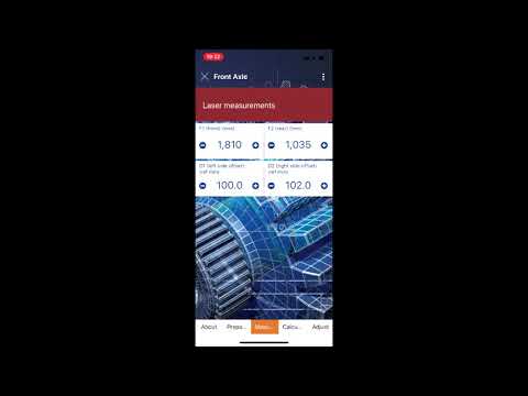
    This is the output from my app...

    Click image for larger version

Name:	Report V26.8 Blue M3 Front V5.JPG
Views:	602
Size:	88.2 KB
ID:	72132

    Then this video explains very briefly how it works...


    Attached Files

    #2
    Nice setup - the big question I always had with jigs like these were how did you get an accurate distance from rotor-to-rotor? I've looked online and found a various numbers for track width from numerous sources so it's hard to know what's accurate. I suppose you could measure the distances between the lasers when they shine forwards and backwards for one axle, then adjust until they are equal (zero toe) and use that as your baseline?

    I recently made up some jigs that use the more traditional string method but should still be fairly accurate. They mount to the car quite sturdily so the string should not move relative to the car:


    And to keep the steering locked on centre I made up a replica of the Turner Motorsport rack alignment tool (haven't had the best of luck with a steering wheel lock due to the guibo):


    Both of these tools will be complemented with leveling pads w/ integrated slip plates that I'll build next year.

    Comment


      #3
      This is cool in theory but all you can do is toe. You have to adjust camber before toe. If you adjust camber, it throws out your toe. I'm an advocate for spending $100 to use the $35000 machines in this case. There a dimples in our rims specifically put their for the Hunter alignment heads. It's just extremely difficult to do something precise without true precision equipment.
      You'll get thrust angle, SAI, caster, camber, and toe just from an alignment machine. Toe is important but so is everything else.
      This is my Unbuild Journal and why we need an oil thread
      https://nam3forum.com/forums/forum/m...nbuild-journal

      "Do it right once or do it twice"

      Comment


        #4
        Thanks Arith2, yes it’s about DIY here and toe related, individual wheel, total, thrust angle, steer ahead.
        Camber I do first by attaching a digital gauge to the axle targets, then as long as I’m on a flat patch, I’ll get good readings. Once camber is set, on the E46, shifting the toe won’t move the camber by any significant degree; a 911 is a different proposition though, where toe and camber are interactive (on the rear axle).
        Views of the new gauge...

        Attached Files

        Comment


          #5
          ]Nice setup - the big question I always had with jigs like these were how did you get an accurate distance from rotor-to-rotor? I've looked online and found a various numbers for track width from numerous sources so it's hard to know what's accurate. I suppose you could measure the distances between the lasers when they shine forwards and backwards for one axle, then adjust until they are equal (zero toe) and use that as your baseline?


          Nice work! Re my rotor-rotor dimension, there’s a lot of mathematics going on in the app, but that dimension is not needed. Bust my head for days re-learning the trig needed, then a day of software testing (my day job). What is handy is the figures created by the app, targets for the laser to hit in order to meet spec or whatever setting you want to go for.

          Comment

          Working...
          X