Much to no one's surprise, I pulled out the aluminum threads holding one of the timeserts in. I'm pretty sure this was the hole I messed up badly, so it was only a matter of time. No big deal though, I left a tooon of material around those holes, so even with a bigsert (~12mm OD on the exterior threads), there's still ~3mm of wall thickness at the thinnest point. Cross section for reference:
Bigsert install was uneventful:
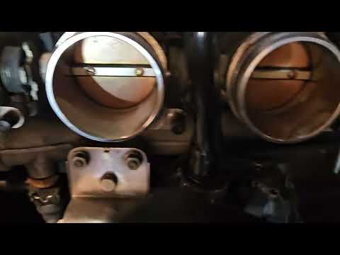
And, importantly, there's no way to tell that something happened with everything back in its place:
Also, pro tip. M8 bigserts use the same bore and threads as M10 regular timeserts. So, if you love to mess up threads (like me) and have a collection of timesert kits, all you need to buy are the bigsert inserts themselves. Then use the M10 timesert drill/tap/counterbore tools and the M8 timesert install tool.


Leave a comment: