I don't have a picture of mine handy, but it's nowhere as bad as that.
Thin film of oil though? Definitely
-
I just installed the blue ECS one....lets see how that does.Originally posted by Slideways View PostLeave a comment:
-
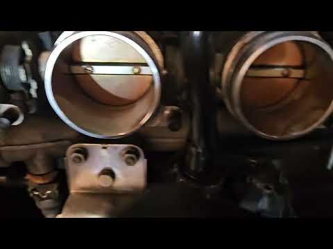
Genuine CSL airbox after about 15k miles with new BMW filterOriginally posted by heinzboehmer View Post

My guess is that the BMC filter allows more flow, but is worse at filtering fine dust particles. Even the non-CSL paper filter allows some stuff to go through, just not nearly as much.Leave a comment:
-
Interesting. The difference in play was super minor, but I guess that might be enough to throw idle off on an engine with ITBs. I've heard people have a tough time getting older ITB engines to idle properly, since getting them all in sync is not easy.Originally posted by bigjae46 View PostLeave a comment:
-
I can't say for certain, but the fit of the filter is pretty bad along the bottom edge. Sand does collect outside the filter lip on the airbox, but there's no obvious sand inside. Might be worth scanning and printing some TPU inserts to seal up the gaps.Originally posted by Bry5on View Post
I wonder if your brake duct scoop is making the sand intrusion situation worse.Leave a comment:
-
Is sand getting past your air filter? I had to add a bunch of foam to get my stock CSL filter to seal against the Karb airbox. Once I did that, no more sand behind the filter
Leave a comment:
-
I was doing a remote dyno tune with Epic Motorsports and he noticed something on the dyno graph. He told me to replace those arms. I didn't notice a difference but apparently it is a common thing and can get bad enough to affect power. I don't know if its the tune or replacing the arms but the car does idle much better now. It would hunt a little bit especially when warming up bit I never cared or tried to address it.Originally posted by heinzboehmer View PostLeave a comment:
-
Also, WOW. Turns out I'm not a shitty driver (I think), it was the car!
Like any good scientist, I changed multiple variables at once before testing, so I'm still not convinced the ICV was fully at fault.
In addition to the ICV, I also swapped in new individual throttle pull rods (13547832148). There really wasn't anything wrong with the ones on the car, but I had new ones on hand, so I took the opportunity to refresh them.
Here's a quick comparison of the play in the pull rods. Cylinder 1 has a new one, 2 and 3 have old ones. Recommend headphones so you can hear the difference, cause it's practically impossible to tell visually:
I didn't even bother taking a picture of new vs old, cause they looked identical.
One thing that did change with the new ones is that the ITBs no longer squeak when actuated! Guess there must have been some crud inside one of the pull rods. I'm surprised this was the cause of the noise, since it's always sounded metallic to me, but I'm not complaining.
Anyway, after doing this work, I cleared idle/throttle adaptations and took the car on the same test route that had triggered the ICV code before. No more codes and driving impressions are all positive. Here's the stuff that most stood out to me:- Throttle tip in is way smoother. I used to feel a subtle bucking that I attributed to slack in the drivetrain, but that's pretty much gone now.
- Pulling away from a stop is also much smoother. I feel like I no longer have to anticipate what the engine will do, since it now does what my foot tells it to. I think the best way to describe this is that it feels like a more modern car now.
- The little bit of remaining weirdness at ~1800 rpm is gone, gone. I'm hoping this was the last remaining difference between mine and Bry5on's car.
- In general, the engine's response to small throttle inputs feels more "rounded". This is a very welcome change.
So even though I didn't fully figure out what was wrong, I do think I solved the issue. I need more seat time to know for sure, but I'm happy for now.Before:
Idle controller adaptation torque: 36.3 Nm
Idle controller start torque: 36.3 Nm
Idle controller start torque with A/C: -24 Nm
Idle controller start air mass: 0.0625 kg/h
After:
Idle controller adaptation torque: 2 Nm
Idle controller start torque: 2 Nm
Idle controller start torque with A/C: 3.2 Nm
Idle controller start air mass: 0.92188 kg/hLeave a comment:
-
I usually spray mine down with electronics parts cleaner, but might need to start doing the soak thing.Originally posted by Obioban View PostLeave a comment:
-

one gallon of this has cleaned all my car’s ICV’s for the last 30 years, whenever I have access to them. Very low effort and cheap preventative.Leave a comment:
-
Weeell, there goes that theory. Managed to prove it wrong two separate ways:- The old valve, with the stator clocked like it was prior to disassembly (I marked it), does not overshoot when given 12V. It can mechanically overshoot, but the motor cogs at the fully closed position, since there's no commutator to keep it spinning until it hits the mechanical limits. I'm guessing the limits are purposefully placed further out to avoid having the pin slam into them every single time. This makes sense.
- I was able to force the new valve to overshoot by pulsing the 12V signal to it, effectively causing a positive feedback loop. Looks like the mechanical stops are in the same place as the old one, but it doesn't overshoot when held at a static voltage because of that same cogging effect.
I should probably stop messing with this and just put the car back together...Leave a comment:
-
Aha!
New genuine valve arrived. Bosch, made in Germany, with a manufacture date of late 2019. As far as I can tell, the design is identical to the one that was original to the car.
I gave it 12V in both directions to observe its limits and found this (apologies for the shitty pics, it was quite hard to hold the valve + wires + phone all at once):
Idle:
Fully open:
Fully closed:
This one doesn't overshoot!
I tried pushing it past its fully closed state with a toothpick, but was unable to. It felt like it was at the mechanical limit.
I can definitely see the DME throwing an error because of this, especially if the control loop is based on RPM/measured air like karter16 confirmed. Flow leading to the error would look something like this:
DME tells valve to fully close -> valve overshoots and lets a little bit of unexpected air in -> RPMs rise -> DME reacts to RPM rise by telling valve to close more -> valve overshoots more and lets more air in -> RPMs rise more -> DME tells valve to close more -> rinse and repeat -> DME gives up and throws an error
I'll get this installed and tested soon. I'll be very happy if this solves my recent low speed jerkiness and it turns out that I do know how to drive stick.Leave a comment:
-
That's wild. I'm surprised that control loop works as well as it does. Would have thought the latency of the feedback would be too high for it to be stable.Leave a comment:
-
I don't think it really needs to - the current duty cycle gives a relative position of sorts, but really the idle controller is a fancy rpm-based feedback loop.Originally posted by heinzboehmer View Post
If RPM below target, increase duty cycle proportionally, evaluate response, continue to adjust, etc.
That's a simplified example, target air mass calculations and all that are in there too, but all inferred from the duty cycle as far as I can tell.Leave a comment:
Leave a comment: