Originally posted by heinzboehmer
View Post
-
Generally the best thermal impedance will come from the smallest air volumes and the lowest gravimetric density you can get away with, so you’re on the right track. I’d probably pick a reasonably high infill personally as the weight penalty isn’t that great. Cubic is a good choice as you definitely want closed cells. You should re-run the Slon test with a desk heater and an IR thermometer! -
Yep! That's the plan. I've been doing some research to see what the optimal infill config would be. At first glance, I would think a fairly high infill percentage would work better, as that would minimize convection in the small air pockets. But then you also get more thermal bridging from the infill walls, so would need to do testing to find the optimum balance.Originally posted by discoelk View Post
However, I did have a thought this morning. "My" design is a 1:1 copy of the stock piece (i.e. same thickness), so if I print it out of a material with similar thermal conductivity to UP-GF, then any amount of air in the interior should result in a lower thermal conductivity.
Quick (unsubstantiated) search says that UP-GF and PET-CF have similar enough thermal properties, so I'll probably just choose an infill with a non-continuous volume (e.g. cubic) and print it with the lowest infill percentage that still results in a strong and dimensionally accurate part.Leave a comment:
-
Depending on the design, you're also getting infill with a 3DP part. So effectively, some open cell "insulation" is created.Leave a comment:
-
Lol, that seems to be the story for all the doing projects I table on this carOriginally posted by George Hill View Post
Just gonna print the part, not a mold.Originally posted by bigjae46 View Post
Rough math says that making it out of carbon + cork core will weigh around the same as the printed part, so not even gonna bother trying. The modern printable materials can take heat really well, so I see no downside to printing.Leave a comment:
-
You're making a mold? Have to be careful with any vertical surfaces. That may cause release issues. Need a slight draft angle...maybe 1-2 degrees?Originally posted by heinzboehmer View Post
Have to factor in exotherm with the mold. Could see up to 200-300 degrees depending on the exact epoxy you use.Leave a comment:
-
Thats amazing! I would so buy this from you once its all done.Leave a comment:
-
Also, this took absolutely forever:
I started with this piece cause it looked simpler than the cabin air filter housing, but, man, was I wrong. Essentially no surface on it is flat, except for the one that butts up against the firewall. Took me a really long time to figure out how to approach all of the curves.
Yes, I realize that a lot of the geometry is there for mold release, but I want to make something that fits all E46s, so I decided to spend the extra time and recreate it as closely as possible. More time spent in CAD land saves me from redesigning the piece down the road if it turns out to not fit on some other chassis configuration.
I also decided to not model the front clip retainer into the piece. I like the idea of using the stock injection molded piece for serviceability. BMW does not sell these separately, so I'm gonna have to go junkyard diving for some. Fortunately, they're just plastic welded in, so they're easy to pop out with a razor blade. This part could also conceivably be recreated, but printing it in a favorable orientation might be tricky.
Also, did some preliminary slicing of the model and the printed version should weigh in at 300-400 g, depending on my choice of material and infill. For comparison, the stock piece weighs in at 1618 g. I do need to split it up into three pieces to fit in my printer, so I'll add some features to bond all of them together nicely. For now, I just added some slicer-generated dowel connectors:
With the stock geometry recreated, I can work on modifying it to accommodate both the braces and the tilted filter. Got some ideas flying around in my mind already for how to approach that. More to come.
Sidenote, since I essentially made a 1:1 replica of the piece, anyone can print it out without modification and save ~1.2 kg. Who's up to be the test fit guinea pig? Hit me up and I'll send you the stl (I'll distribute widely once fitment is validated).Last edited by heinzboehmer; 07-23-2025, 10:31 PM.Leave a comment:
-
Appreciate it!Originally posted by Ramage View Post
It should still make a difference. Hard to quantify how much, but it'll for sure help with strut tower deflection in a similar way as it does on the coupe.
Thanks!Originally posted by 0-60motorsports View Post
Had another friend drive it a few days ago and he was similarly blown away. Hell yeah.Leave a comment:
-
That's amazing! Great workOriginally posted by heinzboehmer View PostLeave a comment:
-
Did a B-A-B test with a friend today and confirmed that I'm not crazy!
Started with the braces on, drove around the block, removed them, drove around the block, put them back on, drove. He was skeptical that they would make much of a difference, but once the car got up to speed (~30 mph), he immediately noticed a difference. He was kinda blown away by how different the car felt to drive with and without the braces. Felt pretty proud when I saw that reaction
Anyway, firewall plug CAD is almost there. Should be able to start cutting/printing soon.Leave a comment:
-
I was thinking something like this combo would work, but I need to take a better look to see if 22mm OD is too big.
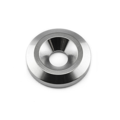
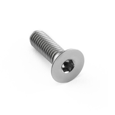
Titanium for the weight saving for my vert...
heinzboehmer apologies for the journal hi-jack
Leave a comment:
-
Thanks!Originally posted by Bry5on View Post
The tabs on mine look like they are plastic, but I guess they could be anodized aluminum.
It also came with this key chain which appears to be made on the same 3D printer that the battery cable holder attached the airbox was made on.
Leave a comment:
Leave a comment: