-
Finally some progress!
Printed out V2 of the firewall plug and its corresponding gaskets. Here are both parts assembled:
The surface finish on the gaskets isn't amazing because of the complicated geometry, but it's more than good enough. If I had a dual extruder machine, printing these out would have been so much easier.
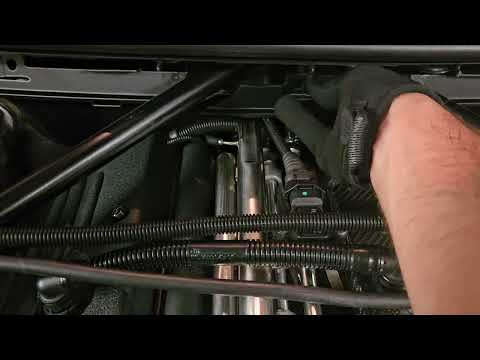
Here it is installed on the car:
Super happy with the fit of these parts, everything lines up great, even the hole for the plastic trim piece by the brake booster:
Here's how the gaskets seal against the braces. Again, super happy with how that worked out:
Now just need to finish up the CAD for the modified cabin air filter housing, get all the parts painted and I'll be able to call this project complete!Leave a comment:
-
That's the one! They were around that price when I started this project as well. Fortunately, they came on every single E85 and E86, so they're not hard to find on eBay (this is how I got mine) or at a junkyard.Originally posted by bigjae46 View PostLeave a comment:
-
The nozzle has been working hard and looks like it died a good death. RIP
V2 of the mold. Lots of learning from V1 and this one came out much better. Still had to tear up the 3D printed part. Need to figure out how to eject parts from the cavity. The threaded inserts are in stock and enroute to me to make the CF part.
Maybe I missed it but is the E86 part number 51717026274? Looks like they are $180 each now. I think this might be a good opportunity to do my first carbon tube project.Last edited by bigjae46; 08-22-2025, 08:02 AM.Leave a comment:
-
Printer is down because I finally killed my nozzle with all the hard-to-print filaments I've ran through it.
Don't think this is supposed to look like that:
While I wait for replacement nozzles to arrive, I've been working on the documentation for the E86 brace retrofit.
Doc is up to almost 50 pages long and I'm still missing a decent chunk of info. I'm trying to write it in such a way that I'll be able to recreate the entire thing even if I lose all memories related to the development of this project. Hopefully, this also means that others can recreate this retrofit without much trouble. Will share more when it's ready.Leave a comment:
-
Awesome! Yep, that's exactly what I should be doing.Originally posted by Obioban View PostLeave a comment:
-
69 pages of build journal. Nice.
Printing my first part in the PETG CF, and I'm loving how it's looking! Thanks for the nudge on that.
... printing straight out of the dryer, as I read it's also hyper moisture sensitive :P
Leave a comment:
-
Man, this TPU is extremely hard to print with.
First off, it absorbs moisture like crazy. Needs to go back in for drying if it's left out for even a few hours.
Also, it's pretty soft, so any tall parts start to flex a lot and ruin the print. I think I've finally managed to find the correct combination of splits, orientations and supports that yields decent parts, but they're far from perfect.
This material is really making me want both a dual extruder machine and one of those fancy drying chambers that you can directly print from.Leave a comment:
-
Muuuch better:
Left is straight out of the box and right is after drying for ~4 hours.
I think I need to experiment with supports or a different orientation. Getting some artifacts in the overhang.Leave a comment:
-
Agreed about the aesthetics of the Slon brace, it looks really nice and similar enough to the BMW performance brace that it doesn't immediately scream aftermarket.Originally posted by D-O View Post
Hard to make a call about damage to the firewall, but the Slon solution has an aluminum, L shaped intermediate piece between the brace and the firewall mount, so I would bet that's gonna suffer more than the firewall. See below for images stolen from Obioban's thread:
I think the chances of any engine bracing making its way into the cabin in a crash are very, very slim. BUT, BMW did it on the E86 and E89 for some reason, so I wanted to emulate it. Like you said, it might be more about preserving the chassis in a crash, but regardless of what the reason is, it definitely makes me sleep better at night .
.
Originally posted by D-O View Post
Most definitely! Still working on the packaging for that, but the filter is absolutely staying. I think airflow across it is likely gonna suffer since space is so tight, but worth it.
Originally posted by D-O View Post
I think so (and Slon's data agrees!). However, it's a much more nuanced difference. Bulkhead increases torsional rigidity by about the same amount, but that's all it does. I find that you kinda need to push the car a bit hard to notice the improvement, with it being most apparent on sudden changes in direction. Also, it's way harder to do an AB test with the bulkhead, so you have to rely entirely on your memory.
However, front triangulation increases chassis rigidity AND limits strut tower deflection. That means three things, which make the change much more noticeable IMO:- You get all the benefits of a stiffer chassis.
- You lose less camber when the front suspension is loaded up in a corner.
- Any loads that were previously going into flexing the strut towers are now going into the steering rack and thus, your hands, which makes the steering feel way nicer.
Leave a comment:
-
The Slon piece really is a work of art - very sexy. When looking at the Slon brace I had not really considered the crash safety factor - just figured if it came in far enough to impale me the accident was likely not survivable anyway. I do wonder if a front impact in the right spot could result in the Slon brace buckling the firewall, turning what might be repairable damage into a total loss. I would be interested to hear if you think this is possible.Originally posted by heinzboehmer View Post
In any case, I do like the factory look you have managed, and it might give me a reason to finally acquire a 3d printer... Is it still the plan to accommodate the cabin filter?
Another question - did the Slon rear bulkhead make as noticeable a difference as the front brace?
Thanks for sharing all the knowledge.Leave a comment:
-
Well, that was fast! Got to me from Spain in two days, crazy:
Bed/layer adhesion is high enough that I was able to print them standing up with no supports. They do flex a little bit when printing the upper layers, but they still come out fine:
I was too impatient to dry the filament before printing, so the surface quality kinda sucks. Drying it out now and will keep messing with the profile to try to make it better.
Fit is excellent though:
Unlike the insert -> plug gasket, these are super chunky and are made to flex a lot to accommodate any slight variations in the angle of the braces. Similar idea to the filter housing -> hood gaskets.
Printed this test piece with 0% infill and it's suuuper flexy, very happy with that:
(the part easily bends with just finger strength, pliers are just there for a clearer picture)
Leave a comment:
-
Printing it standing up helps a LOT with surface quality since you don't get any of the weird interleaved layers on the curved surfaces.Originally posted by Obioban View Post
Kind of a pain to print in this orientation (involves lots of supports), but necessary for strength of the retaining tab in the back.Leave a comment:
-
Really happy with the design of the firewall plug insert. Prototype fits great and the magnets make it snap right into place, can almost just throw it on and it'll go where it needs to:
(tape is only there to hold the magnets in place, didn't want to glue them to the prototype)
Quick video showing how careless you can be when installing, it's pretty great:
Leave a comment:
Leave a comment: