If this is your first visit, be sure to
check out the FAQ by clicking the
link above. You may have to register
before you can post: click the register link above to proceed. To start viewing messages,
select the forum that you want to visit from the selection below.
I’m not exactly a headlight expert, but glare might be the right word to describe it. They’re so damn bright, but the brightness is a little jarring, especially when combined with the cutoff that you CANNOT get into a good spot. The light coming off of reflective signs is very intense, and generally the light coming off of other objects is also intense. I tried a few level adjustments and either you’re blinding cars in front of you, or the cutoff is dropping into the road because of the height of the step in the cutoff. They’d be worlds better if the cutoff was just flat.
My wife’s and my prior Porsches both have/had LED headlights and didn’t experience either of these issues, so I was unpleasantly surprised. These are just as bright, if not brighter, but the execution isn’t fantastic.
I'm no headlight expert either, but the experience you described of light from reflective signs and other objects is what I understand glare means. That was exactly my experience with high color temp headlights. If I ever found myself on an empty highway at night and flicked on my high beams, a good sized sign would be hard to see past.
Not surprised that Porsche's OE headlights mitigate these issues. I'm sure that's an example of the benefits of something that's engineered more-or-less as a whole from the ground up. Higher color temps will always cause more glare and eyestrain, all else equal – but I'm sure managing the beam pattern can do a lot to compensate.
My car really likes v31 of the Mullet Tune™ I was on v26 prior and while cold starts were never hard for my car it would be somewhat lumpy for forty five seconds to a minute first thing in the morning then it would smooth right out. With v31 the car does not have the lumpy cold start and I am also not detecting as strong of a fuel smell from the exhaust (my car is catless) while I let it warm up.
Sounds like those are crap, because the stock headlights are not very good
Glad to hear the review, though, as I've been debating LED conversion to take weight off the nose.
See my note above about your marshmallow headlights.
Worth noting that almost all of the weight reduction is from replacing the ballasts with 3D printed ones. If you’re targeting weight reduction, eliminating them entirely and wiring direct would be the best move. What I did is sort of an 80/20 solution that preserves the factory looking engine bay but drops at least 80% of the weight. The LED headlight itself is about the same weight as the HID+igniter.
Having tried a good range of color temps for headlights, I think my favorite color temp range is something like 3500-3700 K. Above that, I feel like I start losing more to glare than I gain in resolution.
Automotive xenons are generally what, low-to-mid 4000s K? That's pretty much the highest I'll go for.
I’m not exactly a headlight expert, but glare might be the right word to describe it. They’re so damn bright, but the brightness is a little jarring, especially when combined with the cutoff that you CANNOT get into a good spot. The light coming off of reflective signs is very intense, and generally the light coming off of other objects is also intense. I tried a few level adjustments and either you’re blinding cars in front of you, or the cutoff is dropping into the road because of the height of the step in the cutoff. They’d be worlds better if the cutoff was just flat.
My wife’s and my prior Porsches both have/had LED headlights and didn’t experience either of these issues, so I was unpleasantly surprised. These are just as bright, if not brighter, but the execution isn’t fantastic.
Also note that I have non-m headlights, so mine don’t suffer from the toasted marshmallow reflector issues that the M3s had. Both reflectors came out looking perfect with 240k miles on them.
Having tried a good range of color temps for headlights, I think my favorite color temp range is something like 3500-3700 K. Above that, I feel like I start losing more to glare than I gain in resolution.
Automotive xenons are generally what, low-to-mid 4000s K? That's pretty much the highest I'll go for.
The mullet is on v31 now, and thanks to karter16 and all his work, we've got cold start all dialed in now. It was honestly close before but it's pretty on the money now. Plus, Heinz's car now runs right on the same file as mine and the three beta testers on the file are all reporting positive results. We did something good. If you're on an existing one and want the latest, reach out and I'll whip a new file up for you.
Second, I've had a broken-mount passenger headlight for as long as I've owned the car. I finally picked up a replacement and decided to do the NHK LED headlight conversion using nextelbuddy's great DIY video (thank you!) with some minor tweaks. The two tweaks:
1) Doubled up the wiring to the low beams (red+green to positive, black doubled-up to negative) as the wire gauge in the BMW wiring is not quite large enough for the LED headlight wattage. It's fine in the HIDs because the bulb itself runs at higher voltage and therefore lower current.
2) I 3D printed plastic ballast replacements to drop the dead weight that would otherwise be sitting there. Overall I think I dropped 3lbs off the nose.
Honest opinion, I'm not in love with these lights. Yes they're WAY brighter but the color temp is bluer, so they seem less effective with the light output to me. The cutoff is also super weird - it's like a step _| instead of a ramp _/. Not super into it. Not so much that it's worth removing them, but I wouldn't do it again. The stock headlights were pretty damn good.
Also, a 55" TV fits great even with the brace left in place:
I had to use spacers with my SS exhaust too, it fits very poorly. Reused the same spacers with the cabrio brace, no issues there, although I made these spacers myself, so I can’t comment on the SS specific hardware.
I had to use the spacers included with my SS exhaust to get the braces to fit properly with the oversized pipes. Any idea how the convertible brace would work with the SS oversize dual pipe section two?
I had to use spacers with my SS exhaust too, it fits very poorly. Reused the same spacers with the cabrio brace, no issues there, although I made these spacers myself, so I can’t comment on the SS specific hardware.
Fits great! Rough math says that the 4 cabrio fasteners will see about 60% of the load of the original 8, and this brace will certainly be stiffer inherently. So an upgrade on paper. No real noticeable change, but it's definitely not less stiff. It's getting hard to do the driveway test as the car isn't making much creaking in the door sills unless it's pretty extreme.
I had to use the spacers included with my SS exhaust to get the braces to fit properly with the oversized pipes. Any idea how the convertible brace would work with the SS oversize dual pipe section two?
Funny, this is actually what I started on, which led me to the project I chose instead! I went to visit George to grab a scan of that area to design a brace just like that.
It just so happened that the car I was scanning had hit a big pothole on one side so I could see exactly how the metal deformed. Once I’d given that a good look, I was pretty convinced that the flexiness that cracks that strut tower seam sealer is actually coming from where I braced, not directly from where the cracks were forming. So we ran the experiment I posted about earlier to validate the theory. At this point, I think that the brace above would be a bit redundant. I’d bet it would provide incremental gains, but likely much smaller than the invisible ones I installed. Plus, it wouldn’t be invisible So for now I’m pretty happy with where it is.
Wow, thanks for your contribution Bry5on, great read and development! I know there's a guy in europe selling a brace that bolts the shock tower and fender rail. Do you think that would add even more rigidity?
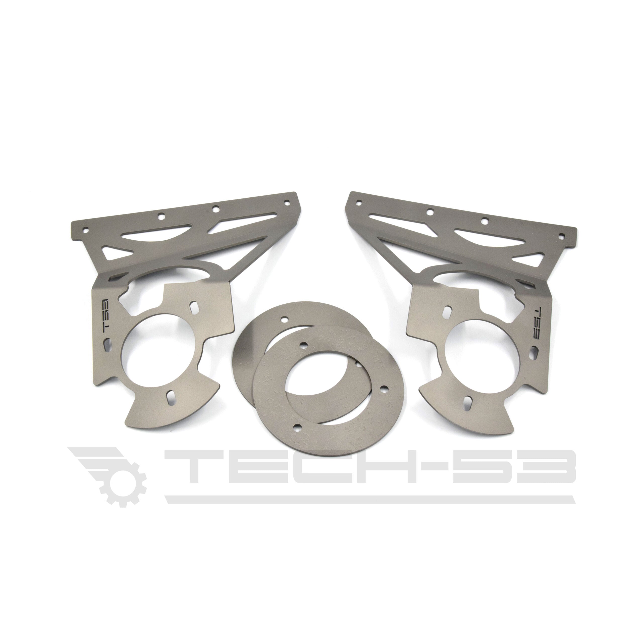
The E46 front strut towers are known to be out of shape, it is one of the car’s weakest point. When the strut towers start to “mushroom,” it means that the metal has begun to deform. It is a result of stress, corrosion, or improper load distribution. This E46 strut tower reinforcemenent kit is the easiest way to fix or


 So for now I’m pretty happy with where it is.
Leave a comment: