Hi all,
I had this journal on the old site, and am now reproducing it here. Probably won't be updating it all at once, but I'll get there. Bear in mind that this journal originally started at the beginning of 2017.
So having owned my M3 for a year last week, and given I'm embarking on some significant work over the next month, I though it was about time I started a build thread.
I got the car in December 2015. I first seriously looked at buying an M3 in 2008, I decided (wisely) to pay off my student loan, etc. first. I then ended up getting married in 2012, and spending some time & money on travel with my wife. In 2015 I was finally ready to start thinking about an M3 again.
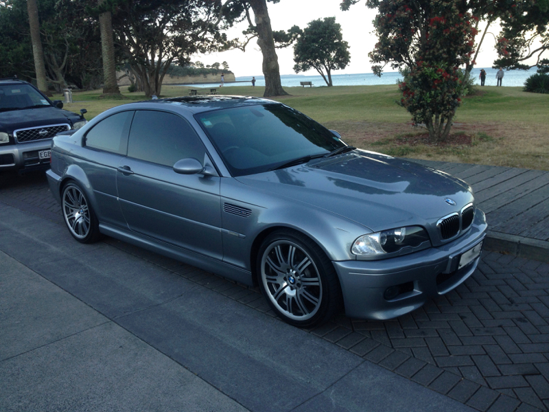
For a number of weeks in August and September I had my eye half-seriously on a 2005 Silver Grey SMG model for sale in my home city (living in New Zealand there's not a huge number of E46 M3's on sale (between 5 and 8 at any one time). I still wasn't really sure if I was ready to buy one or not. Then one day it was sold, and I realised then how much I actually wanted it... I thought that was it and prepared myself to wait until the next one that met my requirements came along. Then, a few weeks later the same car was back on the market. It had actually just been traded between dealers. In the mean time the second dealer had done some work on it (to make it more attractive for sale presumably).
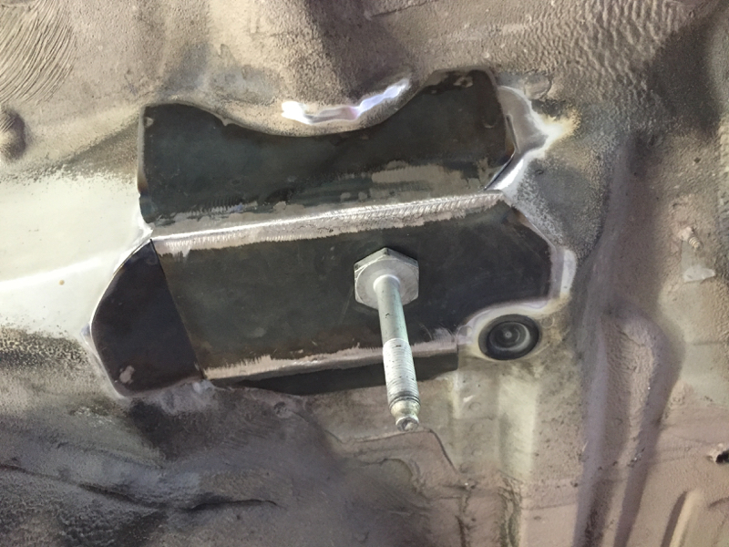
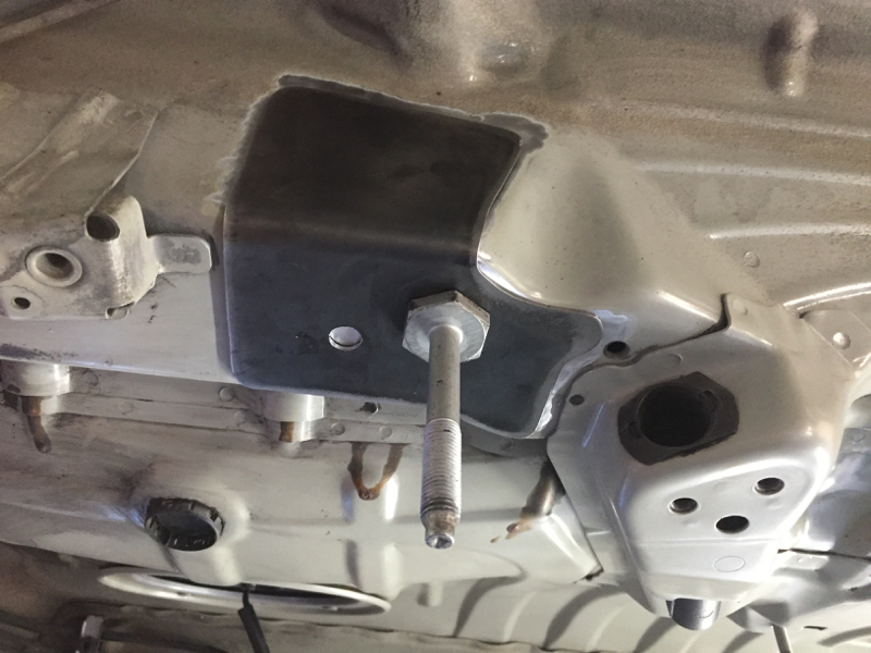
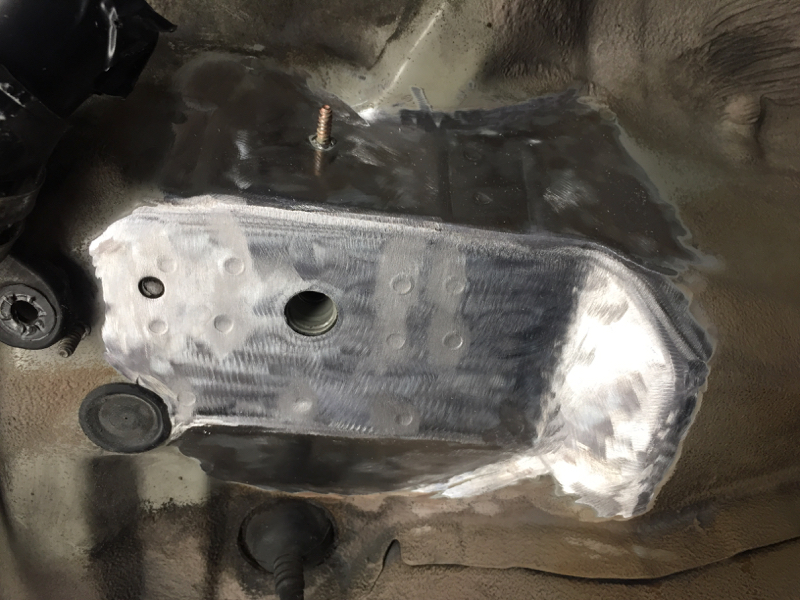
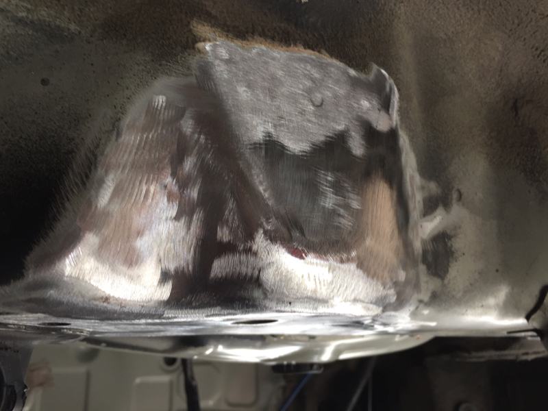
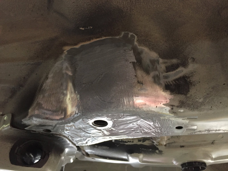
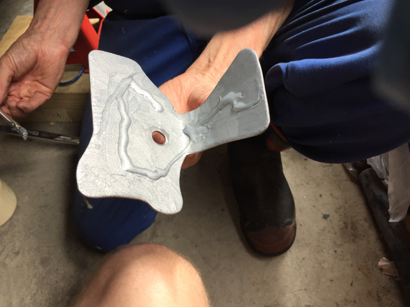
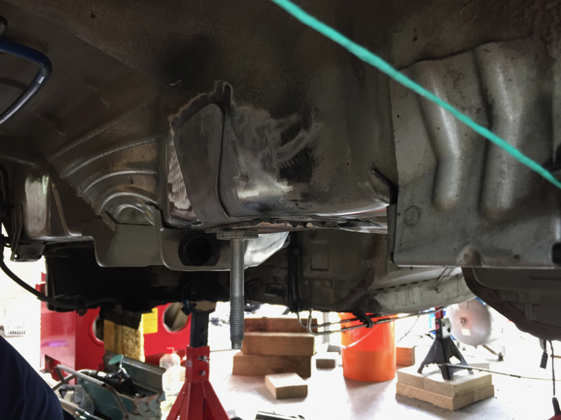
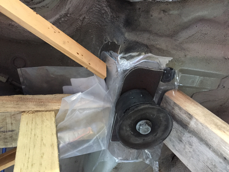
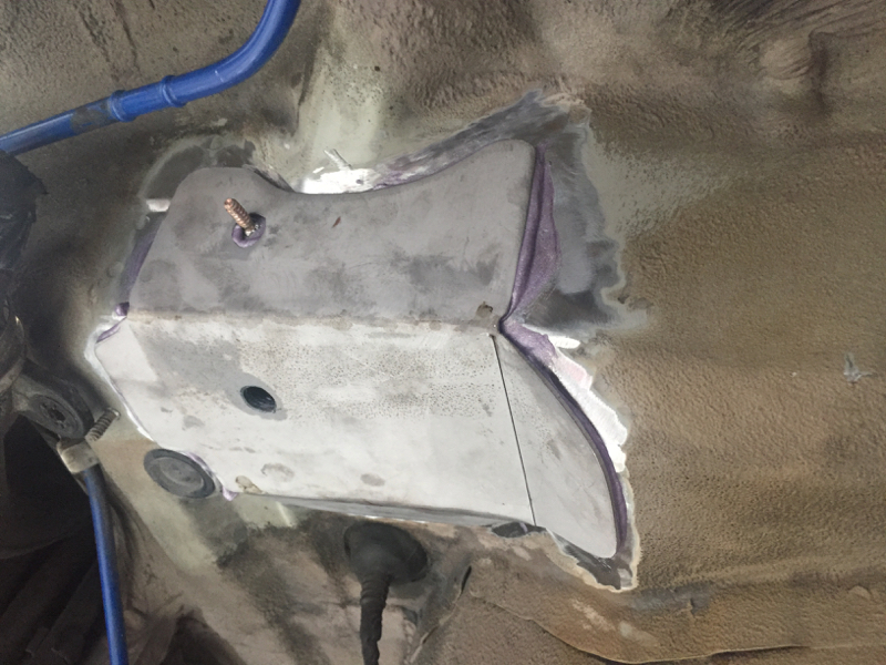
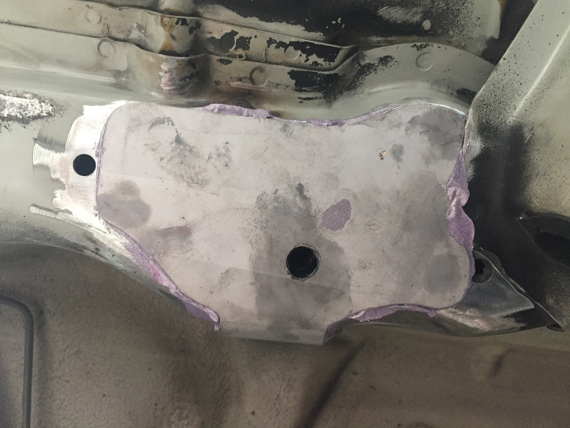
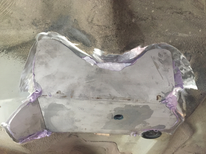
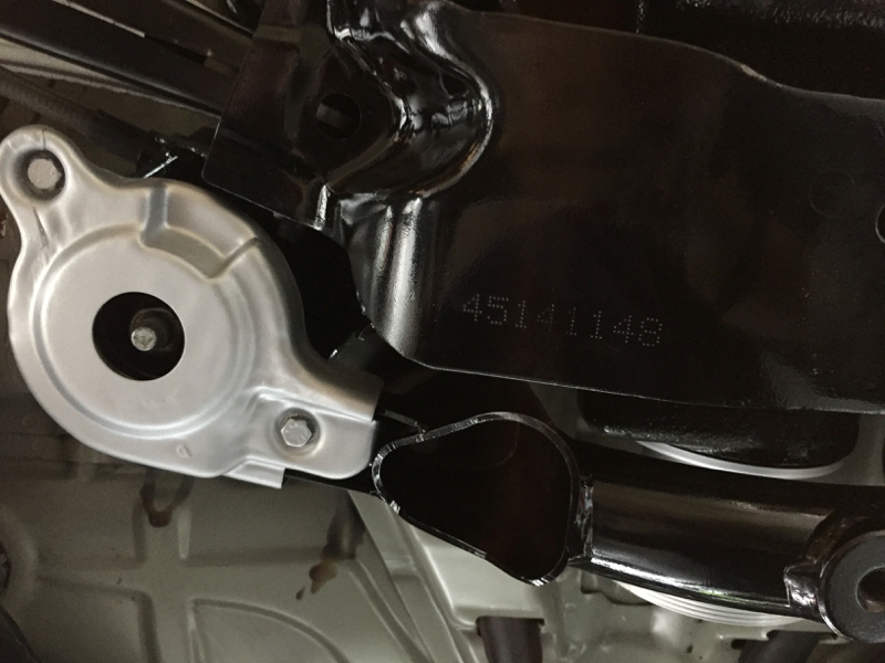
That weekend I went to have a look at it. It was in much better shape that I was expecting. The exterior wasn't perfect, which I was expecting from what others who had looked at it had said. But the interior was in really great condition. More importantly the mechanics of the car seemed to be solid. The car had had the subframe strengthened by BMW NZ, had been serviced at a reputable BMW dealer, and had had things like the RTAB's done a few years previously, which was an indication that the previous owner/s had been taking at least some care of the car.
To make a short story even shorter, I ended up making an offer on the car, and I took it home 3 days before Christmas.
It ticked pretty much all the boxes for me. I was looking for:
I bought it knowing that quite possibly it would need the VANOS done (which indeed it did), but that didn't really bother me. My intent in buying this car was to work on it, maintain it, and make it better than the day I bought it. I plan on keeping this car for a long time, and its an opportunity to learn and develop my mechanics skills as I go. I'm lucky in that regard in that I have my dad to help me. When he was about my age he owned and restored a Daimler SP250, so I'm not exactly on my own on this.
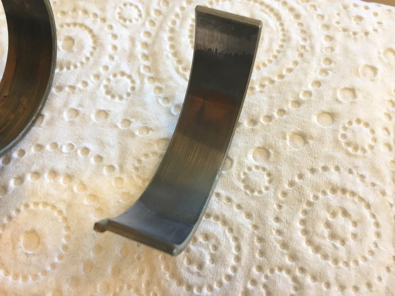
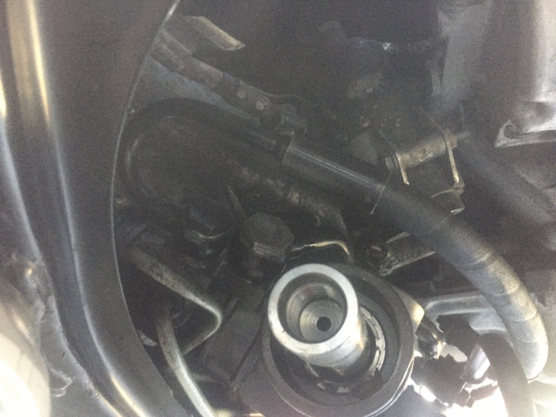
A couple of months after I bought the car I ordered the parts to do the Beisan VANOS rebuild, did the full rebuild, new exhaust disc (existing hub tabs are 100% good), timing chain tensioner, cam bolts, etc. It was a great first project, we spread the work over two days, took our time, and the end result was perfect. All the rattle was gone, and the engine sounded smooth.
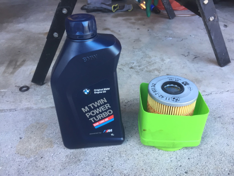
Over the New Zealand winter I didn't get any major work done. did new belts, pulleys and tensioners, and replaced the crank case ventilation separator, but not much else.
Which leads into the present day
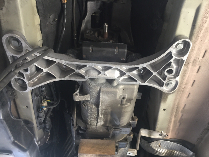
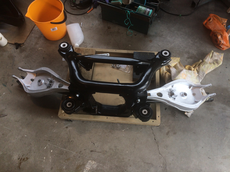
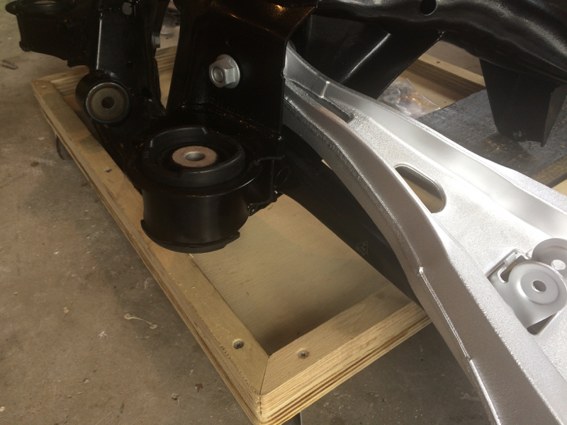
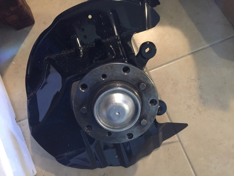
The summer project is a full suspension & bushings rebuild, cleaning up the underside of the car, cleaning, painting, etc. The aim is that the underside of the car will be as close to "like new" as is realistically possible. For me that means:
In New Zealand we don't salt our roads in winter (mostly cause it doesn't get cold enough) so the car is in pretty reasonable condition (more dirt and grime than rush), but if you're under there you might as well do it right hey!
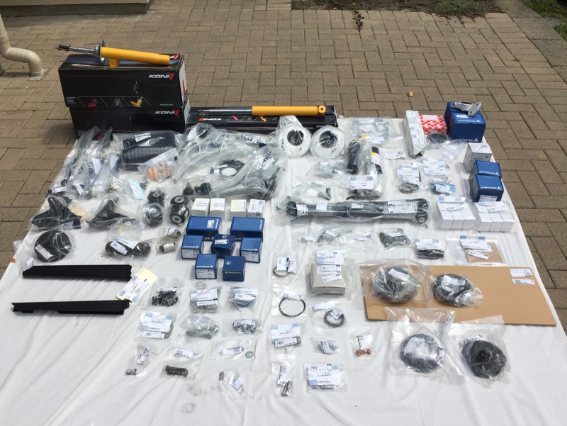
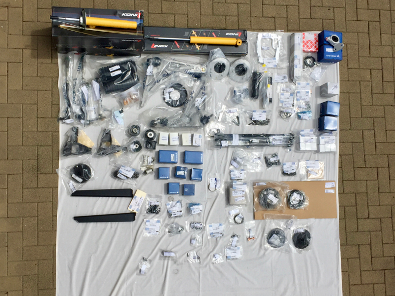
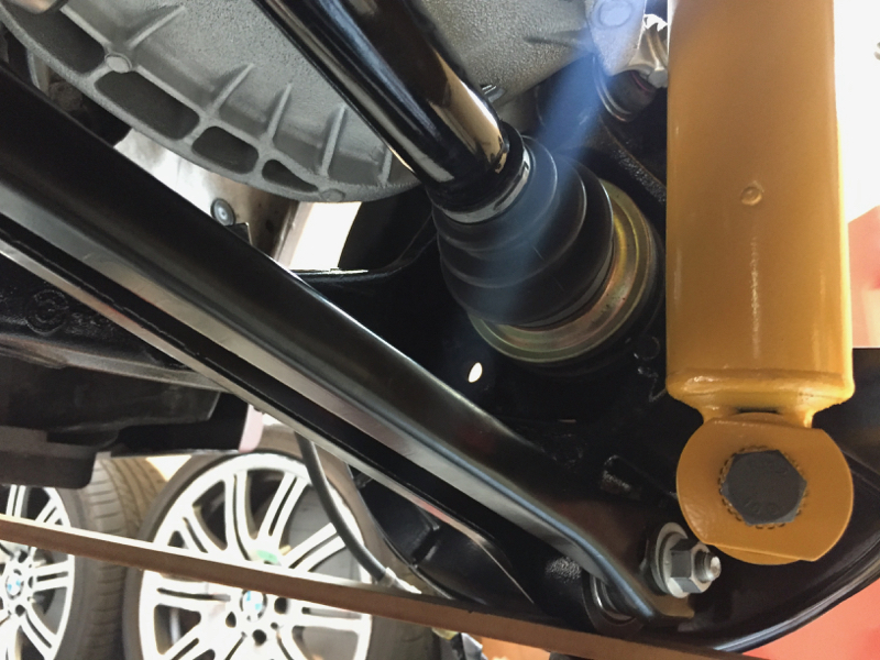
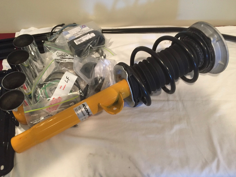
A couple of weeks ago I ordered Koni yellows to replace the stock shocks, as well as about 60 different part numbers for pretty much anything on the underside of the car that looked like it would wear out.
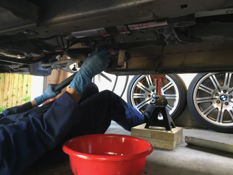
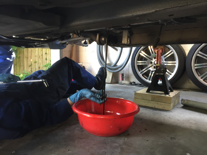
Today Dad and I spent the afternoon getting the car up to working height on jacks (oh for a lift). Over the next few weeks we'll be dismantling, replacing/restoring and rebuilding. I'll be updating here as we go along. Hopefully in a few weeks time the car will be back on the ground and good to go for another 150,000 km :-)
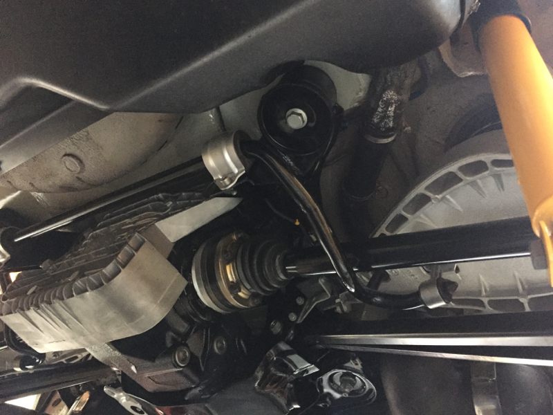
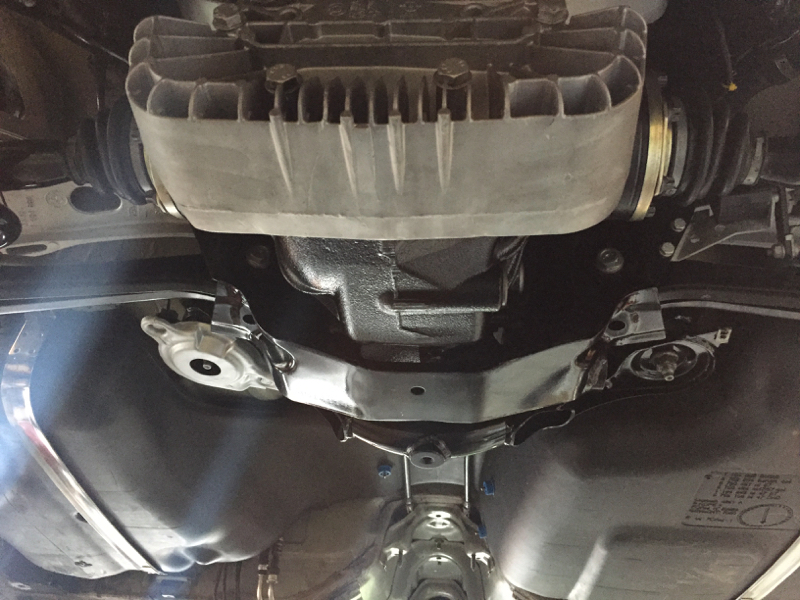
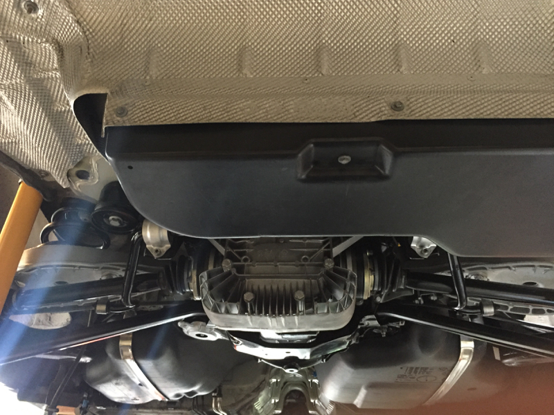
For now I'll end with a pic of the car up on jacks.
I had this journal on the old site, and am now reproducing it here. Probably won't be updating it all at once, but I'll get there. Bear in mind that this journal originally started at the beginning of 2017.
So having owned my M3 for a year last week, and given I'm embarking on some significant work over the next month, I though it was about time I started a build thread.
I got the car in December 2015. I first seriously looked at buying an M3 in 2008, I decided (wisely) to pay off my student loan, etc. first. I then ended up getting married in 2012, and spending some time & money on travel with my wife. In 2015 I was finally ready to start thinking about an M3 again.
For a number of weeks in August and September I had my eye half-seriously on a 2005 Silver Grey SMG model for sale in my home city (living in New Zealand there's not a huge number of E46 M3's on sale (between 5 and 8 at any one time). I still wasn't really sure if I was ready to buy one or not. Then one day it was sold, and I realised then how much I actually wanted it... I thought that was it and prepared myself to wait until the next one that met my requirements came along. Then, a few weeks later the same car was back on the market. It had actually just been traded between dealers. In the mean time the second dealer had done some work on it (to make it more attractive for sale presumably).
- New wing mirror glass on both sides to replace the damaged ones on it.
- All trim parts on the centre console replaced - looked like new.
- New OE brake rotors fitted on the front.
That weekend I went to have a look at it. It was in much better shape that I was expecting. The exterior wasn't perfect, which I was expecting from what others who had looked at it had said. But the interior was in really great condition. More importantly the mechanics of the car seemed to be solid. The car had had the subframe strengthened by BMW NZ, had been serviced at a reputable BMW dealer, and had had things like the RTAB's done a few years previously, which was an indication that the previous owner/s had been taking at least some care of the car.
To make a short story even shorter, I ended up making an offer on the car, and I took it home 3 days before Christmas.
It ticked pretty much all the boxes for me. I was looking for:
- A later manufacturing year (2005/2006).
- SMG (yep I know, but I'm an engineer, SMG is cool, its a differentiator, and I really wanted it).
- Silvergrey or LSB
- Sunroof
- 19in Style 67s
I bought it knowing that quite possibly it would need the VANOS done (which indeed it did), but that didn't really bother me. My intent in buying this car was to work on it, maintain it, and make it better than the day I bought it. I plan on keeping this car for a long time, and its an opportunity to learn and develop my mechanics skills as I go. I'm lucky in that regard in that I have my dad to help me. When he was about my age he owned and restored a Daimler SP250, so I'm not exactly on my own on this.
A couple of months after I bought the car I ordered the parts to do the Beisan VANOS rebuild, did the full rebuild, new exhaust disc (existing hub tabs are 100% good), timing chain tensioner, cam bolts, etc. It was a great first project, we spread the work over two days, took our time, and the end result was perfect. All the rattle was gone, and the engine sounded smooth.
Over the New Zealand winter I didn't get any major work done. did new belts, pulleys and tensioners, and replaced the crank case ventilation separator, but not much else.
Which leads into the present day
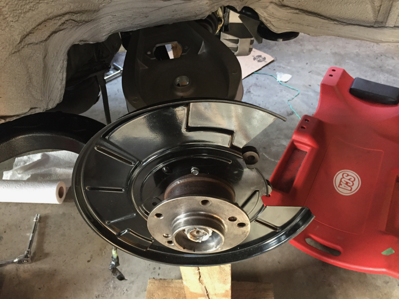
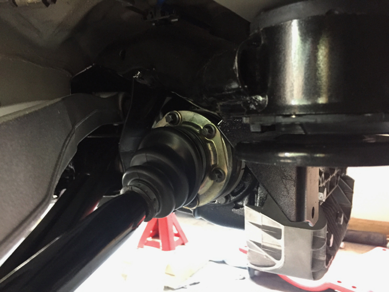
The summer project is a full suspension & bushings rebuild, cleaning up the underside of the car, cleaning, painting, etc. The aim is that the underside of the car will be as close to "like new" as is realistically possible. For me that means:
- Replace parts that wear
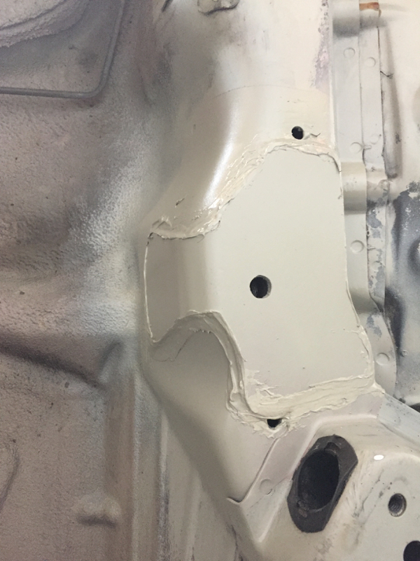
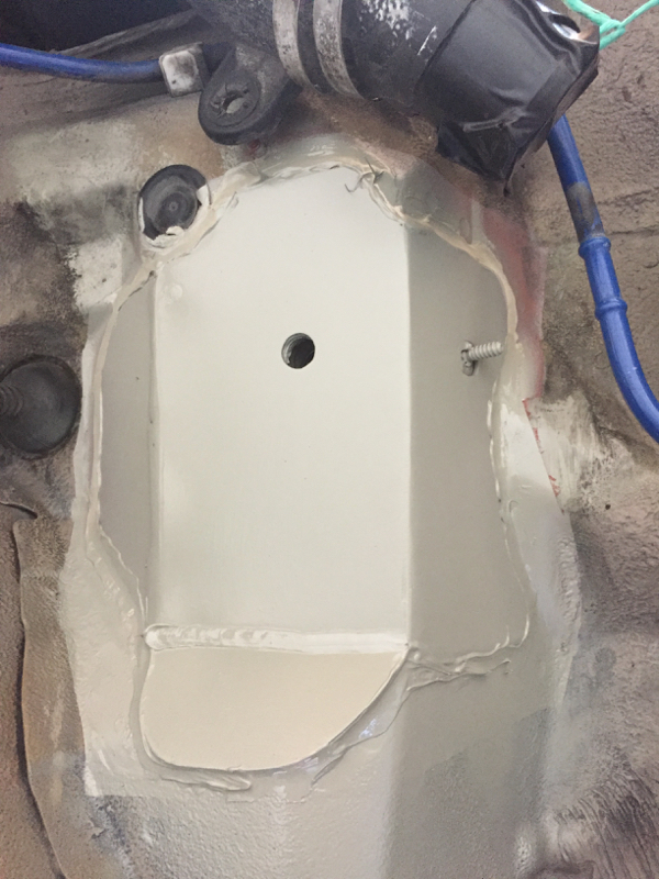
- Clean everything else up
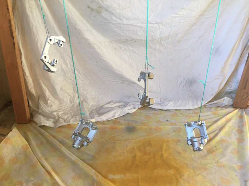
- Seal and paint where appropriate to protect
In New Zealand we don't salt our roads in winter (mostly cause it doesn't get cold enough) so the car is in pretty reasonable condition (more dirt and grime than rush), but if you're under there you might as well do it right hey!
A couple of weeks ago I ordered Koni yellows to replace the stock shocks, as well as about 60 different part numbers for pretty much anything on the underside of the car that looked like it would wear out.
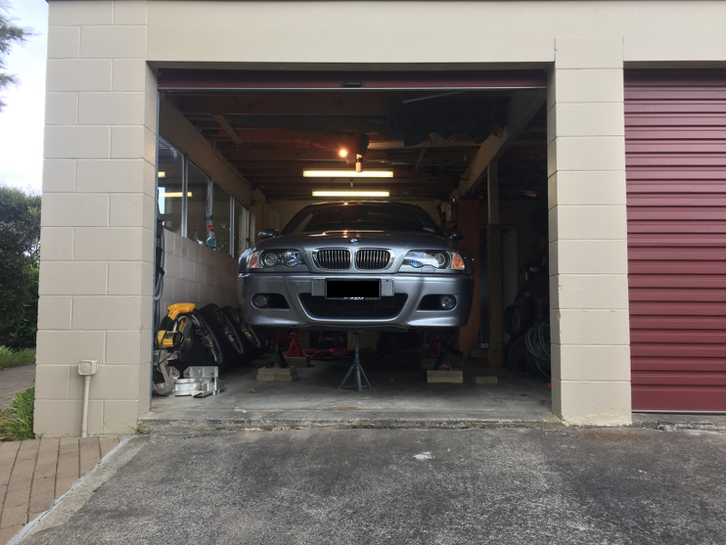
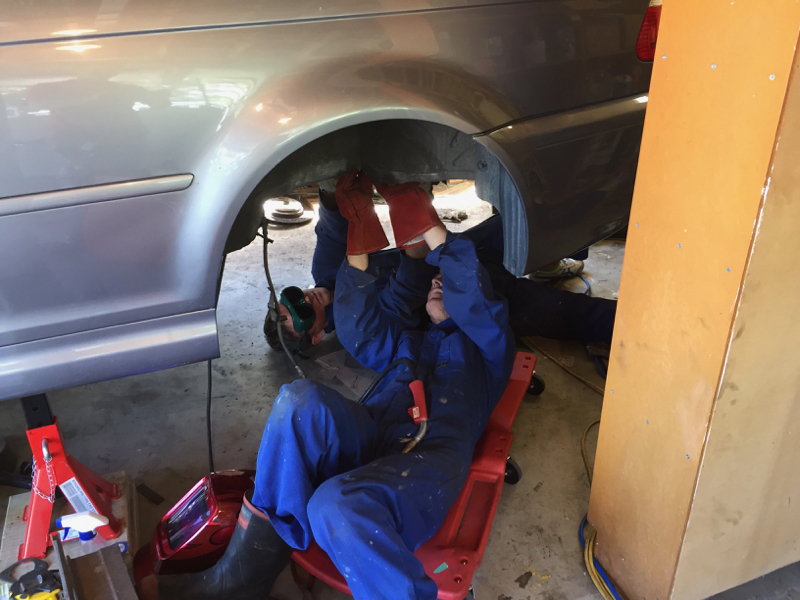
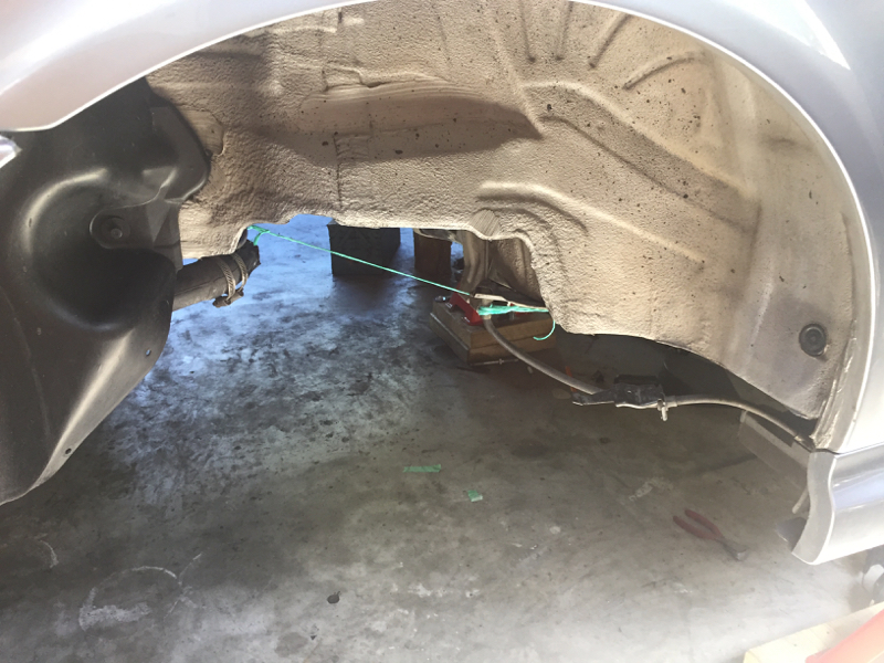
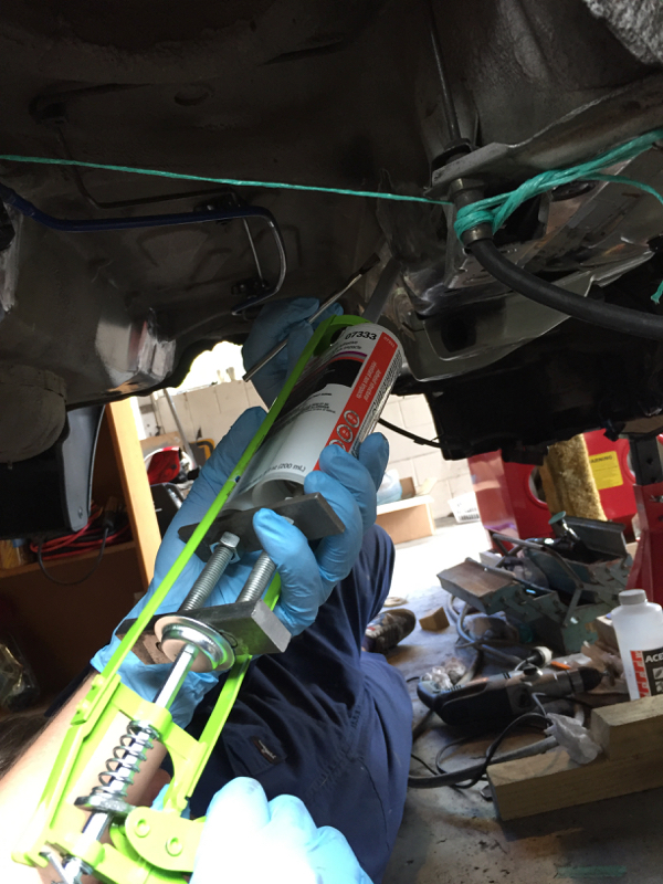
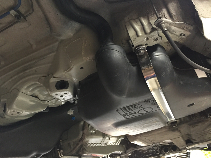
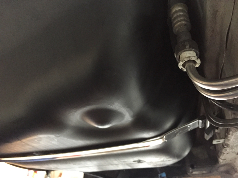
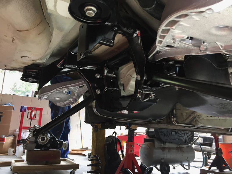
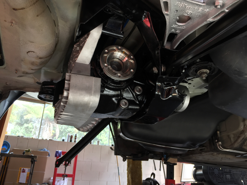
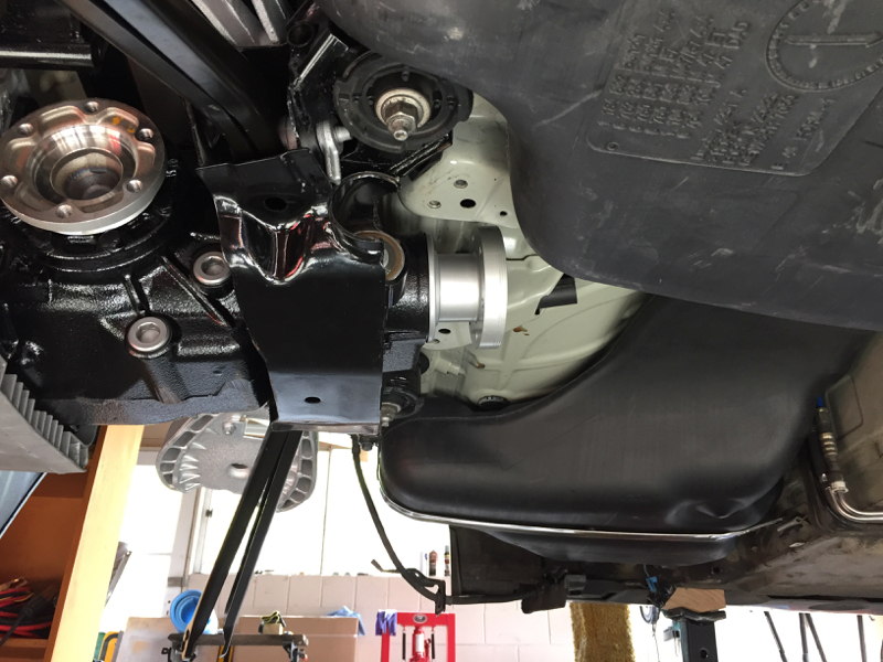
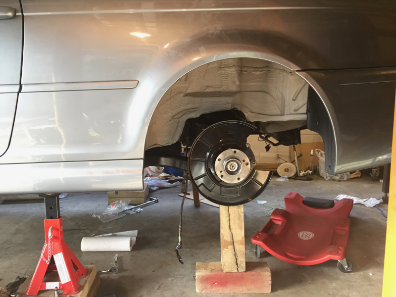
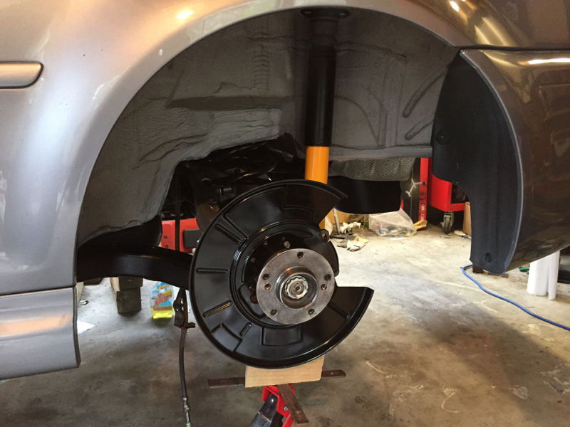
Today Dad and I spent the afternoon getting the car up to working height on jacks (oh for a lift). Over the next few weeks we'll be dismantling, replacing/restoring and rebuilding. I'll be updating here as we go along. Hopefully in a few weeks time the car will be back on the ground and good to go for another 150,000 km :-)
For now I'll end with a pic of the car up on jacks.


 .
.


 arrot:
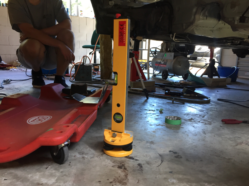


Comment