If this is your first visit, be sure to
check out the FAQ by clicking the
link above. You may have to register
before you can post: click the register link above to proceed. To start viewing messages,
select the forum that you want to visit from the selection below.
Lol, if I didn't want to get this done ASAP, I would 100% take you up on that. A mold for this would fit in the printer, which would make it even easier to make out of CF.
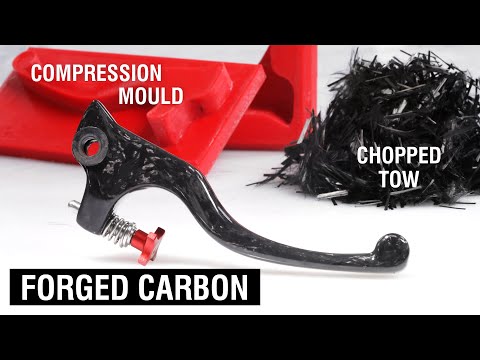
I'm sure this is what you were referring to, but for others benefit...
Lol, if I didn't want to get this done ASAP, I would 100% take you up on that. A mold for this would fit in the printer, which would make it even easier to make out of CF.
Yes, a 3D printed mold eliminate the hardest part of making the mold. The only downside is it tends to not be as durable as a composite mold. Only becomes an issue if the plan is to make a LOT of parts.
I'm sure this is what you were referring to, but for others benefit...
I want to start doing this
Do it! All of the difficulty with compression molds is making the mold and then the math to calculate resin and carbon weights.
EDIT: Google will tell you the density of carbon is 1.7 to 2.0. Stick to 1.4. Learned the hard way. The worst part about working with carbon trimming and finishing. Minimal post work needed - maybe a razor blade and drilling. You do want to use a carbide drill bit (not carbide tipped) which are about $10 to $20 each bit. Use water or a liquid to contain the dust.
I have about 5 lbs of loose carbon strands. Just pay shipping if anyone needs some.
Also fixture is done. Only took 15 hrs to print (!).
As expected, the surface finish on the cuts on the bottom isn't great, since they needed support material:
Again, I'm not going for a flatness record with this, so I'll just clean them up with some high grit sandpaper and it'll be fine.
Assembled (and terribly propped up to show how the cuts are useful):
After holding this piece in my hand, I'm very confident that it'll do great on the mill. It's extraordinarily chunky, I would be very surprised if it fails.
The biggest failure point I can think of are the plastic threads. I added a bunch of wall loops to those areas so they should be fine. Additionally, those are really only there to make sure the strut tower bracket is pressed up against the tops of the posts (i.e. flat), they're not taking much load. Most of that load will be taken by the fasteners threaded in from the bottom into where the stock strut bar studs usually live. I'm definitely not ripping those threads out.
And yes, those are class 12.9 bolts going into 3D printed threads. Gotta make sure the fasteners don't fail!
3D printed fixture worked incredibly well. I could have probably made it half as stiff and it would have still been totally fine. Playing musical bolts to get to the bosses was a bit annoying, but no big deal
Machine operator worked okay. I do have experience on a mill, but this is my first time ever on one without supervision, so go easy on me.
Ended up removing 4.5 mm from bosses to new flat surface. This is 0.75 mm more than I had originally thought I would need, but that's totally fine with me. My brackets will be 4.75 mm thick, so the final assembly will sit pretty much exactly where the stock ones do.
I did forget one thing when designing the fixture. The strut bar surface is angled on two separate axes compared to the strut tower surface, so the fixture needs clearance on the sides as well to be square on the vise when using those two reference cuts I added. Got around that with some creative shimming, but this was far from the stiffest setup, as you can probably tell.
My "lightest of skims" turned into a 0.75 mm cut, which I'm not thrilled with. I fell into the trap of trying to get the surface flat with a subpar setup and removed more than I wanted to. I kinda wish I had just flattened the high spots with a file, but oh well. It shouldn't really make a difference in the end, but lesson learned.
With the final dimensions of the stock brackets known, I jumped into CAD and adjusted my brackets. No big design changes, just some planes moving around a bit:
Also added some extensions to the flanges that were too small for sendcutsend to bend:
And done! They're off to be manufactured now. Next up is finding someone who can weld these up for me.
Last edited by heinzboehmer; 07-02-2025, 09:53 AM.
Are you using a maker space? I had access to one in Wichita, KS. It was outstanding! Wish I had something here in Houston. All the ones I've found require you to be a college student.
Are you using a maker space? I had access to one in Wichita, KS. It was outstanding! Wish I had something here in Houston. All the ones I've found require you to be a college student.
Did this at the machine shop at work.
I'm surprised about the college student thing. Over here, the maker spaces don't care who you are. All they care about are your monthly membership fees
I know I've test fit these things fifty million times now, but having the stock brackets machined got me excited, so I printed up plastic versions of my brackets and fitted everything to the car.
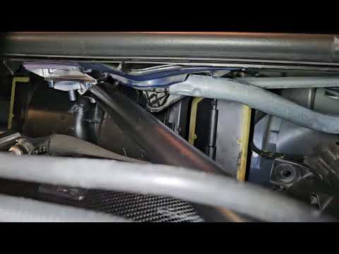
This picture gives a rough idea of how the engine bay will look when everything is ready. I'm a huge fan of how subtle this mod is:
And this one gives a good sense of how tight the clearances are:
Windshield wipers work no problem:
Have tomorrow and Friday off, so I'll scan the engine bay, the cabin air filter housing and the firewall plug. Then get lost in CAD land for a while, figuring out what needs clearancing where.
Also, got this in the mail today:
Will be waiting for me in the stash until the time comes to do my head gasket.
I started this whole project because I didn't like that the Slon brace requires that you remove the strut tower brackets to work on the engine. At this point, I've removed and resintalled my strut tower brackets dozens of times. The irony is not lost on me.
I have to admit I was mistaken. Removing the brackets frequently is nowhere near as annoying as I thought it would be. Yes, there's a chance you can lose your alignment, but as long as you keep the tires on the ground (or plan ahead and temporarily bolt the stock brackets on before lifting the car), it's not a problem at all.
And yes, I've likely spent about as much money developing this as I would have just buying the off the shelf solution.
Still 100% worth it though. I've learned a ton doing this and I really like the subtlety of this solution. Can't wait to have it 100% complete.
3D printed fixture worked incredibly well. I could have probably made it half as stiff and it would have still been totally fine. Playing musical bolts to get to the bosses was a bit annoying, but no big deal
Machine operator worked okay. I do have experience on a mill, but this is my first time ever on one without supervision, so go easy on me.
Ended up removing 4.5 mm from bosses to new flat surface. This is 0.75 mm more than I had originally thought I would need, but that's totally fine with me. My brackets will be 4.75 mm thick, so the final assembly will sit pretty much exactly where the stock ones do.
I did forget one thing when designing the fixture. The strut bar surface is angled on two separate axes compared to the strut tower surface, so the fixture needs clearance on the sides as well to be square on the vise when using those two reference cuts I added. Got around that with some creative shimming, but this was far from the stiffest setup, as you can probably tell.
My "lightest of skims" turned into a 0.75 mm cut, which I'm not thrilled with. I fell into the trap of trying to get the surface flat with a subpar setup and removed more than I wanted to. I kinda wish I had just flattened the high spots with a file, but oh well. It shouldn't really make a difference in the end, but lesson learned.
With the final dimensions of the stock brackets known, I jumped into CAD and adjusted my brackets. No big design changes, just some planes moving around a bit:
Ok...now I get what you are trying to do. Skim the OE part, make a layer that the thinner OE part can sit on that will provide the mounting point for the E86 bars. I know...I'm dense sometimes or at least that's what my wife tells me...lol
Ok...now I get what you are trying to do. Skim the OE part, make a layer that the thinner OE part can sit on that will provide the mounting point for the E86 bars. I know...I'm dense sometimes or at least that's what my wife tells me...lol
Yep! That's exactly it. I have a bunch of left over adhesive from the windshield mount, so I'll likely bond the skimmed OE part to my custom part, for that last little bit of extra stiffness.
Just need to figure out how to combine that with powder coating. I haven't found a reference where 3M outright states the operating temp range that 07333 is intended to work at, but the data sheet seems to imply that it shouldn't be exposed to temps higher than 80 C. Might need to get everything painted instead of powder coated because of this, we'll see.


Comment